Wednesday, October 22, 2014
How to Make a Frequency Generator
How to Make a Frequency Generator. On cloud busters Fredbuster created a wonder tutorial for getting started and building your own Zapper. Fredbusters Tutorial in PDF-Based off his design here is how I made my frequency generator.
Frequency Generator Circuit Diagram


Parts Needed

1 Project box with PC board included,
1 Compositor 1 micro farad, C2, I like the un-polarized because it allows you not to worry about positive an negative sides. If you do get one with a longer leg thats the positive, see schematic for proper placement.
1 Compositor .01 micro farad, C1
1 LED 1-3 volt, small red ones. Remember the longer leg is the positive, connect properly,
1 Resistor 3.3k ohm, R1, It will say it on the upper part figuring out the colors is a pain. See photo below for product ID.
1 Resistor 3.9k ohm R4
1 Resistor 4.7k ohm R5
1 Resistor 1k ohm R3 for creating a body zapper with pennies,
1 resistor for R2 see Fredbusters PDF file for specific resistor for frequency. I use variable potentiometers because I like to set exact frequencies myself. I use 100k potentiometers, they give me a range from 6hz to 460hz when adjusting. You can see in the below photo I have both the large audio and micro potentiometers. The micro is used to be set at 15hz and the Audio is for creating variable.
1 on/off switch for the battery
1 toggle switch for the switching between 15hzand variable. Thats how I like to do mine.
1 555CN timer chip, make sure its the one that can handle up to 18 volts. The CMOS 555 can only handle low voltage and is easily shorted out.
1 8 pin IC Socket, just incase you burn out your 555 you can replace it without creating another circuit.
2 9 volt battery plugs, I like 2 because it lasts longer and has more amperage. One will do fin though.
Black and Red 22 gauge connecting wire, Make sure its the one with multiple threads of copper and not a solid one. Its easier to bend and move. The solid copper connecting wire is to kinky and breaks to easily, for my taste.
1 spool of Solder, The thinner the better, for getting into tight spaces and heats up better.
1 Solder Iron, A pin point will be needed for this circuit.
1 1/8" audio phone jack, I like them because they make the box look clean and its and easy size to attach to any other devices.

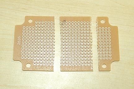


First we take the PC board that was included with the Black box and break it into a size we need.
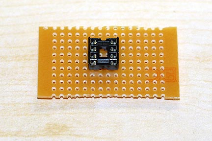
Next we place the 8 pin bracket in the middle.
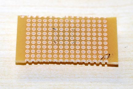
Notice on the back how I bend over the pins to hold it in place.
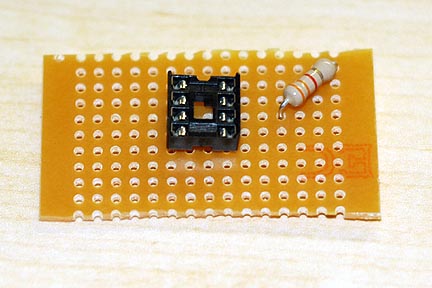
Next we attach R1 3.3k resistor. One end goes to pin 8 and the other to pin 7, I bend the legs over the pin then cut off 1/4" longer than the distance to the pin. the remaining 1/4" I bent over and stick in the pin hole. see schematic.
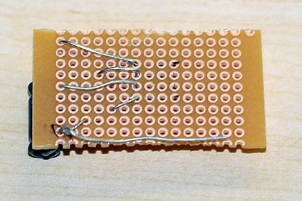
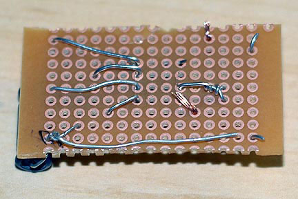
Here is how it looks on the back.
Next we attach Compositor C2 1.0 mf, and Compositor C1 0.001 mf. C2 connects to pin 6 and the base of C1. C1 connects to pin 5 and C2 base.
Here is how it looks on the back, notice how the base of C1 and C2 are twisted together.
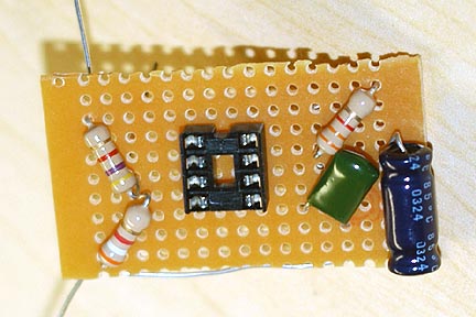
Next we add R4 3.9k and R5 4.7k to the board.
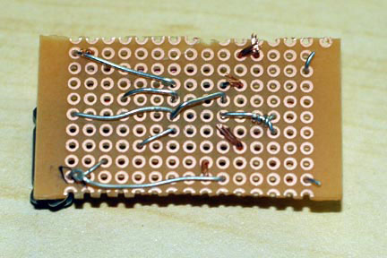
Notice on the back the ends are twisted together and connected to Pin 3.
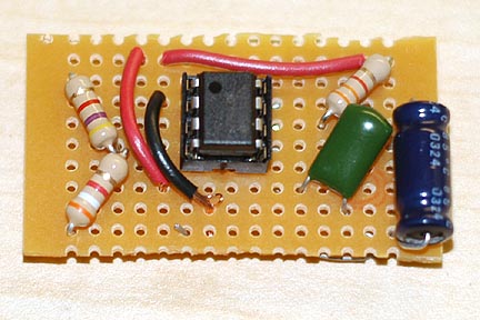
Here is when I added the 555 timer, make sure the black dot is in the upper left corner.
Using one of the wire ends I cut off from the excess of the resistors I connect Pin 2 to Pin 6. like so.
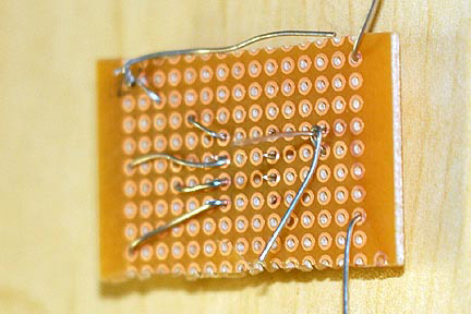
Now is when I start adding the wires to hook up the positive and negative connections.
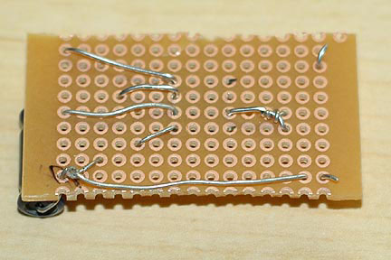
Back of circuit.
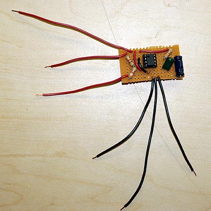
Now for the wires that hook up to LED, Output jack and switches.
You can see how I soldered the connections together. Make sure you are clean and accurate. Other wise a lose connection or overlapping solder will cause the circuit not to work. This takes patients and time, dont rush it. If you do overlap a connection with solder, heat it up, use another wire to suck up the excess and then use a knife to remove the last bits. I heat the wires first then add the solder. Its cleaner once you get used to soldering. Takes practice.
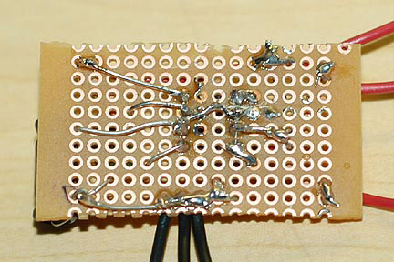
Here is what the final circuit looks like before its place in a box. You can see the R2 I added here. I use a toggle switch to go back and forth between the set resistor and variable resistor. One end of the resistor is connected to R1 where it attaches to pin 7. The middle Pin on the Potentiometer is then connected to a toggle switch. The Middle switch pin is then connected to C2 where it attaches to pin 6. Using potentiometers allows you to set a frequency you want. In Fredbusterstutorial he gives you the specific resistor for specific frequency.
Here are links to four photos showing detailed enlargement of the circuit with the variable potentiometers added and how they are connected. This should explain how I connected the potentiometers.
http://www.ryanmcginty.com/orgone/frontcircuitlg.jpg
http://www.ryanmcginty.com/orgone/backcircuitlg.jpg
http://www.ryanmcginty.com/orgone/beforeboxback.jpg
http://www.ryanmcginty.com/orgone/beforebox.jpg
Next I begin placing the circuit into the box. I slip the LED wires thru to the outside because thats how you hook up this specific light. I used shrink tubing to seal the connection keeping them not from touching other wires.
You can see how I drilled the holes to fit each switch, LED and output jack. This is how I have the circuit placed inside the box. Notice the blank area to hold the two 9 volt batteries. I prefer two 9v because it allow the Freq Gen to run longer. About 14 days nonstop at 15hz.
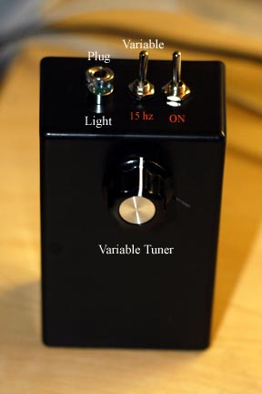
And finally how the frequency box looks when finished. Notice I dont have penny electrodes because this box is only to power OR devices and not kill body parasites. Copy the circuit drawing above and you can have both.
Radioshack sells a digital voltage meter which has a setting for frequencies. It cost me about $50. It works great. All I do is connect the output from the generator to the meter’s input wires. Instantly it says the exact frequency the dial is tuned too. If you don’t have voltage meter and work around the house repairing things yourself this is a must have.
To put the set the frequencies I use my computer. I use the 1/8" stereo jack into my sound card, making sure the input volume is on low. Use a Sound generator program and match the tones. Make sure the sound wave is set to square. It takes time to get it right but it works.
On a good day it takes me 1 hour and half to make the whole thing. It will cost you about $40 to 45 in parts to make one like mine.
Sourced By: Ryan
Subscribe to:
Post Comments (Atom)
No comments:
Post a Comment