Showing posts with label from. Show all posts
Showing posts with label from. Show all posts
Tuesday, November 18, 2014
Make a series letters from the LED
Make a series letters from the LED , Things to consider before making the sign of the LED array,
1) Use LED nodes.
2) Paint the top of the PCB with a dark color (black).
3) Note the LED specifications. In this experiment use a 5mm diameter LED nodes
that emit red, specification voltage of 3 volts.
The assembly of LED:
1) One letter composed at most 5 columns and 7 rows.
2) One column mostly composed by 6 LEDs are arranged series.
3) Then the fifth column are connected in parallel.
Here is one letter LED scheme.
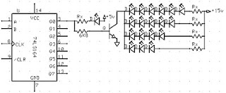
Medium picture below is the lay out of the 2-letter nameplate. To make the sign 8 letter, copied from a second stay this letter.

Example of LED on the letters A and B:

Read More..
1) Use LED nodes.
2) Paint the top of the PCB with a dark color (black).
3) Note the LED specifications. In this experiment use a 5mm diameter LED nodes
that emit red, specification voltage of 3 volts.
The assembly of LED:
1) One letter composed at most 5 columns and 7 rows.
2) One column mostly composed by 6 LEDs are arranged series.
3) Then the fifth column are connected in parallel.
4) Each column given the constraints, Rx, which amount depends on the number of LEDs in one column and depends also on the type of LED (in this experiment that used LED 5mm in diameter, clear with red light beam).
5) In a column consisting of 6 LEDs, Rx = 330 ohm, 5 LEDs, Rx = 560 Ohms, 4 LEDs, Rx = 680 Ohms Remember, this provision applies to 5 mm LED red light beam nodes.
6) Every letter was given FCS9013 transistor amplifier. Here is one letter LED scheme.
Medium picture below is the lay out of the 2-letter nameplate. To make the sign 8 letter, copied from a second stay this letter.
Example of LED on the letters A and B:
Value Rx in the first and the fifth column (letter A) of 560 ohms, because it consists of 5 LEDs are arranged series. Rx in the second column, third, and fourth, amounting to 680 ohms because it consists of two LEDs.
Rx first column letter B, 330 ohms. Rx second column, third, fourth, and fifth at 680 ohms.
Thursday, October 30, 2014
USB Keyboard Made from Old Typewriter
Looking for a unique gift? Here’s an antique typewriter which has been modified to function as a USB Keyboard for PC, Mac, or even iPad. That’s very cool, isn’t it?
In the world of obsolescence, this USB typewriter is a groundbreaking innovation. It does not change the outward appearance of the typewriter and is easy to install since there is no messy wiring. The 3 components of the USB typewriter are the Sensor board, the USB switches, and the Reed Switches.
It works like a regular typewriter with all letters, numerals, and punctuation marks as well as shift, space, and return carriage. It’s a better addition to your home office.
It works like a regular typewriter with all letters, numerals, and punctuation marks as well as shift, space, and return carriage. It’s a better addition to your home office.
Wednesday, October 8, 2014
Door Alarm Hangs up on the door handle Beeps when someone touches the door handle from outside
Door Alarm
Hangs up on the door-handle

Parts:
R1______________1M 1/4W Resistor R2______________3K3 1 or 2W Resistor (See Notes) R3_____________10K 1/2W Trimmer Cermet (See Notes) R4_____________33K 1/4W Resistor R5____________150K 1/4W Resistor R6______________2K2 1/4W Resistor R7_____________22K 1/4W Resistor R8______________4K7 1/4W Resistor C1,C2__________10nF 63V Ceramic or Polyester Capacitors C3_____________10pF 63V Ceramic Capacitor C4,C6_________100nF 63V Ceramic or Polyester Capacitors C5______________2µ2 25V Electrolytic Capacitor C7____________100µF 25V Electrolytic Capacitor D1,D2,D4_____1N4148 75V 150mA Diodes D3_____________5 or 3mm. Red LED Q1,Q2,Q3,Q5___BC547 45V 100mA NPN Transistors Q4____________BC557 45V 100mA PNP Transistor L1_________________ (See Notes) L2_____________10mH miniature Inductor Hook_______________ (See Notes) BZ1___________Piezo sounder (incorporating 3KHz oscillator) SW1,SW2________SPST miniature Slider Switches B1_______________9V PP3 Battery Clip for PP3 Battery
Device purpose:
This circuit emits a beep and/or illuminates a LED when someone touches the door-handle from outside. The alarm will sound until the circuit will be switched-off.
The entire circuit is enclosed in a small plastic or wooden box and should be hanged-up to the door-handle by means of a thick wire hook protruding from the top of the case.
A wide-range sensitivity control allows the use of the Door Alarm over a wide variety of door types, handles and locks. The device had proven reliable even when part of the lock comes in contact with the wall (bricks, stones, reinforced concrete), but doesnt work with all-metal doors.
The LED is very helpful at setup.
Circuit operation:
Q1 forms a free-running oscillator: its output bursts drive Q2 into saturation, so Q3 and the LED are off. When part of a human body comes in contact with a metal handle electrically connected to the wire hook, the body capacitance damps Q1 oscillations, Q2 biasing falls off and the transistor becomes non conducting. Therefore, current can flow into Q3 base and D3 illuminates. If SW1 is closed, a self-latching circuit formed by Q4 & Q5 is triggered and the beeper BZ1 is activated.
When the human body part leaves the handle, the LED switches-off but the beeper continues to sound, due to the self-latching behavior of Q4 & Q5. To stop the beeper action, the entire circuit must be switched-off opening SW2.
R3 is the sensitivity control, allowing to cope with a wide variety of door types, handles and locks.
Notes:
L1 is formed winding 20 to 30 turns of 0.4mm. diameter enameled copper wire on R2 body and soldering the coil ends to the resistor leads. You should fill R2 body completely with coil winding: the final turns number can vary slightly, depending on different 1 or 2W resistor types actual length (mean dimensions for these components are 13-18mm. length and 5-6mm. diameter).
The hook is made from non-insulated wire 1 - 2mm. diameter (brass is well suited). Its length can vary from about 5 to 10cm. (not critical).
If the device is moved frequently to different doors, Trimmer R3 can be substituted by a common linear potentiometer fitted with outer knob for easy setup.
To setup the device hang-up the hook to the door-handle (with the door closed), open SW1 and switch-on the circuit. Adjust R3 until the LED illuminates, then turn slowly backwards the screwdriver (or the knob) until the LED is completely off. At this point, touching the door-handle with your hand the LED should illuminate, going off when the hand is withdrawn. Finally, close SW1 and the beeper will sound when the door-handle will be touched again, but wont stop until SW2 is opened.
In regular use, it is advisable to hang-up and power-on the device with SW1 open: when all is well settled, SW1 can be closed. This precautionary measure is necessary to avoid unwanted triggering of the beeper.
Subscribe to:
Posts (Atom)