Showing posts with label led. Show all posts

Tuesday, November 18, 2014

Make a series letters from the LED

Make a series letters from the LED , Things to consider before making the sign of the LED array,
1) Use LED nodes.
2) Paint the top of the PCB with a dark color (black).
3) Note the LED specifications. In this experiment use a 5mm diameter LED nodes
that emit red, specification voltage of 3 volts.

The assembly of LED:
1) One letter composed at most 5 columns and 7 rows.
2) One column mostly composed by 6 LEDs are arranged series.
3) Then the fifth column are connected in parallel.
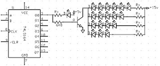
4) Each column given the constraints, Rx, which amount depends on the number of LEDs in one column and depends also on the type of LED (in this experiment that used LED 5mm in diameter, clear with red light beam).
5) In a column consisting of 6 LEDs, Rx = 330 ohm, 5 LEDs, Rx = 560 Ohms, 4 LEDs, Rx = 680 Ohms
Remember, this provision applies to 5 mm LED red light beam nodes.
6) Every letter was given FCS9013 transistor amplifier.

Here is one letter LED scheme.
Make


Medium picture below is the lay out of the 2-letter nameplate. To make the sign 8 letter, copied from a second stay this letter.

Make


Example of LED on the letters A and B:

Make

Value Rx in the first and the fifth column (letter A) of 560 ohms, because it consists of 5 LEDs are arranged series. Rx in the second column, third, and fourth, amounting to 680 ohms because it consists of two LEDs.
Rx first column letter B, 330 ohms. Rx second column, third, fourth, and fifth at 680 ohms.
Read More..

Digital Led Chaser circuit diagram

Digital Led Chaser circuit diagram

This particular circuit employs electronic digital circuits say for example a demultiplexer and also a binary table to build designs of "moving" led lights. This simple circuit is actually awesome while employed in the dark or light up an indicator of a few type, because it produces a awesome design which attracts the eyesight.

The primary component of the circuit is a demultiplexer 74ls138, we can be connected minimally important bits on the output on the counter, which will pick out one of many pins of the demultiplexer as being the output, lighting effects the led connected to the item. The counter can be wired only to be counted, plus a time clock beat is necessary to do that operate (the time clock circuit isnt involved, but almost any can do, if it is not very noisy)

One variation to apply is to connect the most major bit of that counter to a different a line leds, allowing and also disabling one of these so the design could observe 16 leds instead of the only 8 established these.
Read More..

Saturday, November 8, 2014

LED Christmas Star

This circuit can be used to construct an attractive Christmas Star. When we switch on this circuit, the brightness of lamp L1 gradually increases. When it reaches the maximum brightness level, the brightness starts decreasing gradually. And when it reaches the minimum brightness level, it again increases automatically. This cycle repeats. The increase and decrease of brightness of bulb L1 depends on the charging and discharging of capacitor C3. When the output of IC1 is high, capacitor C3 starts discharging and consequently the brightness of lamp L1 decreases. IC2 is an opto-isolator whereas IC1 is configured as an astable multivibrator. The frequency of IC1 can be changed by varying the value of resistor R2 or the value of capacitor C1.


Remember that when you vary the frequency of IC1, you should also vary the values of resistors R3 and R4 correspondingly for better performance. The minimum brightness level of lamp L1 can be changed by adjusting potentiometer VR1. If the brightness of the lamp L1 does not reach a reasonable brightness level, or if the lamp seems to remain in maximum brightness level (watch for a minute), increase the in-circuit resistance of potmeter VR1. If in-circuit resistance of potmeter VR1 is too high, the lamp may flicker in its minimum brightness region, or the lamp may remain in off state for a long time. In such cases, decrease the resistance of potmeter VR1 till the brightness of lamp L1 smoothly increases and decreases. When supply voltage varies, you have to adjust potmeter VR1 as stated above, for proper performance of the circuit. A triac such as BT136 can be used in place of the SCR in this circuit. Caution: While adjusting potmeter VR1, care should be taken to avoid electrical shock.
Read More..

Friday, November 7, 2014

40 LED Bicycle Light

The 555 circuit below is a flashing bicycle light powered with four C,D or AA cells (6 volts). Two sets of 20 LEDs will alternately flash at approximately 4.7 cycles per second using RC values shown (4.7K for R1, 150K for R2 and a 1uF capacitor). Time intervals for the two lamps are about 107 milliseconds (T1, upper LEDs) and 104 milliseconds (T2 lower LEDs). Two transistors are used to provide additional current beyond the 200 mA limit of the 555 timer. A single LED is placed in series with the base of the PNP transistor so that the lower 20 LEDs turn off when the 555 output goes high during the T1 time interval. The high output level of the 555 timer is 1.7 volts less than the supply voltage.

Adding the LED increases the forward voltage required for the PNP transistor to about 2.7 volts so that the 1.7 volt difference from supply to the output is insufficient to turn on the transistor. Each LED is supplied with about 20mA of current for a total of 220mA. The circuit should work with additional LEDs up to about 40 for each group, or 81 total. The circuit will also work with fewer LEDs so it could be assembled and tested with just 5 LEDs (two groups of two plus one) before adding the others.
Read More..

Thursday, October 30, 2014

LED Flashlight Use Supercapacitor


Bored of playing around with capacitors? Then its time for you to move on to super-capacitors. These have huge storage capabilities. In this article you will find out how to build a small LED flashlight using supercapacitors.

LED

The main disadvantage of capacitors is their large voltage drop. For this project, a minimum voltage of 2 volts is required to light the LED. As a result, the “Joule Thief” design would be incorporated here. Using this, a AA battery can be used to light an LED till it is completely discharged.
In this case, a supercapacitor would be taking the place of the battery. Here an LED is used to perform the function of a diode. This ensures that there is sufficient voltage across the LED.

LED

The requirements of the project are listed below:
  • White LED
  • Super capacitor (10F, 2.7 V)
  • Transistor
  • Torus
  • 1 k ohm resistor
  • Wires
  • Breadboard

The torus and the transistor used here comes from an energy-saving lamp HS. Care should be taken while removing this from the lamp as a breakage could result in the release of the mercury vapors. A lamp load along with a USB port is added to the circuit. This makes it compatible with a PC or a car radio.

LED

 A few precautions have to be taken while constructing the circuit. The USB port should not be provided with excess power. The capacitor does not withstand a high voltage and hence a zener diode is connected in parallel to handle the high voltage. The diode protects the capacitor when the voltage exceeds a certain value.
Read More..

Wednesday, October 29, 2014

Temperature Candle Using LED

LED based projects require a lot of skill and hence only experienced circuit designers try out these circuits. But there are also a few circuits in this genre that can be done by amateur electronic hobbyists. The temperature candle is one such circuit. Read on to know more about this.


The hardware components that are required to build this circuit are listed below:
  • Microcontroller
  • Temperature Sensor
  • RGB LED
  • PCB

The circuit design is pretty simple. The LED is made to flicker by the microcontroller and the color is based on the ambient temperature at that point. The temperature of the room can be known by observing the color of the LED.

The temperature value is obtained in degree Celsius. This value is received as a result of pressing the reset button on the PCB. This value can also be obtained by providing power to the device. Once the device is powered up, the change in temperature is indicated. The blue LED is triggered for a temperature increase of 10 degrees. The red LED is triggered for a temperature increase of a single degree.
Suppose, the ambient temperature is 23 degrees celsius, The circuit works in such a way that the blue LED is made to blink twice and the red LED is made to blink 3 times. Soon after this, an orange colored flicker is observed as the LED goes into canfle mode.

Since through hole components are used in this circuit, it is very cheap to construct and the components can be easily soldered. The circuit also contains a jack for connecting to a Microchip Pickit 3 programmer / debugger. This reduces the complexity involved in code modification and download.
Read More..

Saturday, October 25, 2014

LED Clock Using PIC 11 SP

Now youll be able to perpetually grasp the precise time. With this style youll be able to have an atomic clock in your area. Isn’t that great? scan on to grasp additional.


First of all, its not regarding any radioactive components here. this can be regarding building a clock show that may get the time from the DCFF77 facilities in Frankfurt, Germany.All thats required may be a clock LED show, DCFF77 receiver, and a microcontroller at the side of the mandatory connections.

Basically, the project permits a sign thats sent by the DCFF77 radio station to be decoded. After that. the microcontroller method it and sends it to the LED show to indicate the precise time. theres no got to build a sign receiver, an honest quality receiver may be bought on the net for a coffee worth.


Once everything has been set within the affiliation board the PIC supply code ought to be developed. The orientation of the antenna ought to be perpendicular to Frankfurt. itll receive signal if its among 2000 miles from town. If theres a sign, the amount on the clock LED show can blink during a constant rhytm. When a full cycle of binary pulses is received, the clock can show the precise time.
Read More..

Monday, October 20, 2014

1 Watt LED em AC Circuit Diagram

The circuit 1Watt LED for AC LED uses a 1 Watt Luxeon LED white, its voltage is 3.6 volts and consumes 350 mA at maximum. It is important to note that this circuit can generate a lethal shock if handled carelessly. Most of the points are on the network, so that care should be taken when handling.

1 Watt LED em AC Circuit Diagram

1 Watt LED em AC Circuit Diagram

Read More..

Wednesday, October 1, 2014

Simple LED Voltmeter Circuit

This LED voltmeter circuit, although simple, is capable of accurate voltage measurement. The input is applied to the high impedance input of lC1 via the attenuator comprising of R1 to R5 inclusive.
Since this IC is used as a unity gain buffer, the output at pin 6 is equal to the input voltage at pin 3, but at a low impedance. lC2 is connected as a comparator driving a pair of LEDs, D1 and D2. The inverting input samples a portion of the unknown input voltage, whilst the non—inverting input is connected to a 1V reference obtained from the stable voltage across ZD1. ln use RV1 is adjusted till D2 just illuminates. At this point, if the control knob is of the 0 - 10 calibrated type, the pointer will indicate the input voltage. ‘   For example, with SW1 in position 2, and with a reading of 2 on RV1, the input voltage will be 2V. With a little practice, the     voltage can be read to 1-2%, comparable to a moving coll instrument. The input lmpedance on all ranges is 3.2M.

  The circuit shows how an LM39OON amplifier may be employed to compare two input voltages and to indicate the result by means of a small lamp. lf the input voltage connected to the non- inverting input is appreciably more positive than the other input, the output of the amplifier will provide a positive voltage which renders the TR2conducting. The lamp will then be illuminated. One of the inputs may be a reference voltage so that one can then compare a single input voltage against this constant reference.

 
Read More..

Wednesday, September 24, 2014

How to Reuse Old Cell Battery for LED lighting

Normally cell batteries have a shelf life of 2 to 5 years under normal use. After that time we have to replace them. Nowadays there replacement batteries which are cheap, but these batteries last for much less cost only months. An easy solution is to use batteries in a circuit that requires less current, we can use them for lighting LEDs.

 How to Reuse Old Cell Battery for LED lighting 

How to Reuse Old Cell Battery for LED lighting

Read More..

Thursday, September 18, 2014

40 LED Bicycle Light

The 555 circuit below is a flashing bicycle light powered with four C,D or AA cells (6 volts). Two sets of 20 LEDs will alternately flash at approximately 4.7 cycles per second using RC values shown (4.7K for R1, 150K for R2 and a 1uF capacitor). Time intervals for the two lamps are about 107 milliseconds (T1, upper LEDs) and 104 milliseconds (T2 lower LEDs). Two transistors are used to provide additional current beyond the 200 mA limit of the 555 timer. A single LED is placed in series with the base of the PNP transistor so that the lower 20 LEDs turn off when the 555 output goes high during the T1 time interval. The high output level of the 555 timer is 1.7 volts less than the supply voltage.

Circuit  Project: 40 LED Bicycle Light

Adding the LED increases the forward voltage required for the PNP transistor to about 2.7 volts so that the 1.7 volt difference from supply to the output is insufficient to turn on the transistor. Each LED is supplied with about 20mA of current for a total of 220mA. The circuit should work with additional LEDs up to about 40 for each group, or 81 total. The circuit will also work with fewer LEDs so it could be assembled and tested with just 5 LEDs (two groups of two plus one) before adding the others.

Circuit Source: DIY Electronics Projects
Read More..

DUAL 3v WHITE LED FLASHER DUAL 1v5 WHITE LED FLASHER


This circuit alternately flashes 2 white LEDs, on a 3v supply and produces a really bright flash. The circuit produces a voltage above 5v if the LED isnt in circuit however the LED limits the voltage to its characteristic
voltage of three.2v to 3.6v.   The circuit takes concerning 2mA and is actually a voltage-doubler (voltage incrementer) arrangement.

The 1k charges the 100u and therefore the diode drops zero.6v to prevent the LED from setting out to illuminate on 3v. When a transistor conducts, the collector pulls the 100u down towards the 0v rail and therefore the negative of the electro is actually concerning 2v below the 0v rail. The LED sees 3v + 2v and illuminates terribly brightly when the voltage reaches about 3.4v.  All the energy within the electro is pumped into the LED to supply a really bright flash.

DUAL 1v5 WHITE LED FLASHER

This circuit alternately flashes 2 white LEDs, on a 1.5v supply and produces a really bright flash. The circuit
produces a voltage of concerning 25v when the LEDs dont seem to be connected, however the LEDs scale back this as they need a characteristic voltage-drop across them after they are illuminated. dont use a offer voltage above one.5v.

The circuit takes concerning 10mA. The transformer consists of thirty turns of terribly fine wire on a 1.6mm slug 6mm long, however any ferrite bead or slug will be used. the amount of turns isnt crucial. The 1n is very important and using the other worth or connecting it to the positive line can increase the provision current.
Using LEDs apart from white can alter the flash-rate considerably and each LEDs should be identical color.

Read More..

Tuesday, September 9, 2014

AC 230V Led Wiring diagram Schematic by DIAC

This is a very simple LED flasher schema diagram that is powered from AC 230V mains. This Flasher can be used as a power indicator for the AC 230V mains supply. This schema is made with few numbers of parts namely, a LED, two Resistors, one Capacitor, one Diode and one DIAC.  The DIAC act the main role to flashing the LED. DIAC is a bidirectional device. It conducts current only after its breakover voltage has been reached its threshold. Most DIACs breakover voltage is around 30 V.

230V Mains Power Indicator LED Flasher Circuit Diagram


When mains is connect to the schema, the Capacitor(C1) starts charging through Diode(D1)&Registor(R1). When the voltage on the capacitor reached the DIAC’s threshold voltage, the DIAC get turn on. And LED gets Lights(flash). At the same time Capacitor(C1) goes discharges and breakover voltage of DIAC also decrease and LED turns OFF. The on off time of the LED depends on the value of Capacitor(C1)  and Resistor(R1).

Note that the flashing time of the LED shown in the animating figure is not the exact timing of ON/OFF.


Copyright : CircuitsTune.com

Read More..

Wednesday, September 3, 2014

1 Watt LED em AC Wiring diagram Schematic

The schema 1Watt LED for AC LED uses a 1 Watt Luxeon LED white, its voltage is 3.6 volts and consumes 350 mA at maximum. It is important to note that this schema can generate a lethal shock if handled carelessly. Most of the points are on the network, so that care should be taken when handling.

1 Watt LED em AC Circuit Diagram

1

Read More..

Friday, August 22, 2014

LED or Lamp Pulsar Circuit


This schema operates a LED in pulsing mode, i.e. the LED goes from off state, lights up gradually, then dims gradually, etc. This operation mode is obtained by a triangular wave generator formed by two op-amps contained in a very cheap 8 pin DIL case IC. Q1 ensures current buffering, in order to obtain a better load drive. R4 & C1 are the timing components: using the values shown in the parts list, the total period is about 4 seconds.


Parts:

R1 = 4.7K
R2 = 4.7K
R3 = 22K

R4 = 2.2M
R5 = 10K
R6 = 47R

C1 = 1µF-63V

Q1 = BC337

D1 = Red Led

IC1 = LM358


Notes:


* The most satisfying results are obtained adopting for R4 a value ranging from 220K to 4M7. * Adopting for R4 a value below 220K, the pulsing effect will be indistinguishable from a normal blinking effect. * The LED can be any type and color. * You can use a filament lamp bulb instead of the LED, provided it is rated in the range 3.2 to 6V, 200mA max. * Using a bulb as a load, R6 must be omitted. * Voltage supply range can be 4 to 6V: 4.5V is the best compromise. * Do not supply the schema with voltages exceeding 6V: it will work less good and Q1 could be damaged when a bulb will be used as the load. * At 6V supply, increase R6 value to 100 Ohm.

Read More..

Tuesday, August 19, 2014

LED Torch


We can see when we use torches we cant use it for long time but here I have mention a schema. it shows the way of using a long life L.E.D torch.It gives 80 times longer service.Than normal Torch.


Note

# If you want to use different voltage you can do these modifications.

# Change R3 values as follows, according to the power.

9V - 470 Ohm
12V - 560 Ohm
Read More..