Showing posts with label make. Show all posts
Showing posts with label make. Show all posts
Tuesday, November 18, 2014
Make a series letters from the LED
Make a series letters from the LED , Things to consider before making the sign of the LED array,
1) Use LED nodes.
2) Paint the top of the PCB with a dark color (black).
3) Note the LED specifications. In this experiment use a 5mm diameter LED nodes
that emit red, specification voltage of 3 volts.
The assembly of LED:
1) One letter composed at most 5 columns and 7 rows.
2) One column mostly composed by 6 LEDs are arranged series.
3) Then the fifth column are connected in parallel.
Here is one letter LED scheme.
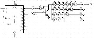
Medium picture below is the lay out of the 2-letter nameplate. To make the sign 8 letter, copied from a second stay this letter.

Example of LED on the letters A and B:

Read More..
1) Use LED nodes.
2) Paint the top of the PCB with a dark color (black).
3) Note the LED specifications. In this experiment use a 5mm diameter LED nodes
that emit red, specification voltage of 3 volts.
The assembly of LED:
1) One letter composed at most 5 columns and 7 rows.
2) One column mostly composed by 6 LEDs are arranged series.
3) Then the fifth column are connected in parallel.
4) Each column given the constraints, Rx, which amount depends on the number of LEDs in one column and depends also on the type of LED (in this experiment that used LED 5mm in diameter, clear with red light beam).
5) In a column consisting of 6 LEDs, Rx = 330 ohm, 5 LEDs, Rx = 560 Ohms, 4 LEDs, Rx = 680 Ohms Remember, this provision applies to 5 mm LED red light beam nodes.
6) Every letter was given FCS9013 transistor amplifier. Here is one letter LED scheme.
Medium picture below is the lay out of the 2-letter nameplate. To make the sign 8 letter, copied from a second stay this letter.
Example of LED on the letters A and B:
Value Rx in the first and the fifth column (letter A) of 560 ohms, because it consists of 5 LEDs are arranged series. Rx in the second column, third, and fourth, amounting to 680 ohms because it consists of two LEDs.
Rx first column letter B, 330 ohms. Rx second column, third, fourth, and fifth at 680 ohms.
Saturday, October 25, 2014
Make a Photodiode Alarm
This Photodiode based Alarm can be used to give a warning alarm when someone passes through a protected area. The circuit is kept standby through a laser beam or IR beam focused on to the Photodiode. When the beam path breaks, alarm will be triggered.
The circuit uses a PN Photodiode in the reverse bias mode to detect light intensity. In the presence of Laser / IR rays, the Photodiode conducts and provides base bias to T1. The NPN transistor T1 conducts and takes the reset pin 4 of IC1 to ground potential. IC1 is wired as an Astable oscillator using the components R3, VR1 and C3. The Astable operates only when its resent pin becomes high. When the Laser / IR beam breaks, current thorough the Photodiode ceases and T1 turns off. The collector voltage of T1 then goes high and enables IC1. The output pulses from IC1 drives the speaker and alarm tone will be generated.
The circuit uses a PN Photodiode in the reverse bias mode to detect light intensity. In the presence of Laser / IR rays, the Photodiode conducts and provides base bias to T1. The NPN transistor T1 conducts and takes the reset pin 4 of IC1 to ground potential. IC1 is wired as an Astable oscillator using the components R3, VR1 and C3. The Astable operates only when its resent pin becomes high. When the Laser / IR beam breaks, current thorough the Photodiode ceases and T1 turns off. The collector voltage of T1 then goes high and enables IC1. The output pulses from IC1 drives the speaker and alarm tone will be generated.
Photo-Diode Alarm Circuit


Wednesday, October 22, 2014
How to Make a Frequency Generator
How to Make a Frequency Generator. On cloud busters Fredbuster created a wonder tutorial for getting started and building your own Zapper. Fredbusters Tutorial in PDF-Based off his design here is how I made my frequency generator.
Frequency Generator Circuit Diagram


Parts Needed

1 Project box with PC board included,
1 Compositor 1 micro farad, C2, I like the un-polarized because it allows you not to worry about positive an negative sides. If you do get one with a longer leg thats the positive, see schematic for proper placement.
1 Compositor .01 micro farad, C1
1 LED 1-3 volt, small red ones. Remember the longer leg is the positive, connect properly,
1 Resistor 3.3k ohm, R1, It will say it on the upper part figuring out the colors is a pain. See photo below for product ID.
1 Resistor 3.9k ohm R4
1 Resistor 4.7k ohm R5
1 Resistor 1k ohm R3 for creating a body zapper with pennies,
1 resistor for R2 see Fredbusters PDF file for specific resistor for frequency. I use variable potentiometers because I like to set exact frequencies myself. I use 100k potentiometers, they give me a range from 6hz to 460hz when adjusting. You can see in the below photo I have both the large audio and micro potentiometers. The micro is used to be set at 15hz and the Audio is for creating variable.
1 on/off switch for the battery
1 toggle switch for the switching between 15hzand variable. Thats how I like to do mine.
1 555CN timer chip, make sure its the one that can handle up to 18 volts. The CMOS 555 can only handle low voltage and is easily shorted out.
1 8 pin IC Socket, just incase you burn out your 555 you can replace it without creating another circuit.
2 9 volt battery plugs, I like 2 because it lasts longer and has more amperage. One will do fin though.
Black and Red 22 gauge connecting wire, Make sure its the one with multiple threads of copper and not a solid one. Its easier to bend and move. The solid copper connecting wire is to kinky and breaks to easily, for my taste.
1 spool of Solder, The thinner the better, for getting into tight spaces and heats up better.
1 Solder Iron, A pin point will be needed for this circuit.
1 1/8" audio phone jack, I like them because they make the box look clean and its and easy size to attach to any other devices.


First we take the PC board that was included with the Black box and break it into a size we need.
Next we place the 8 pin bracket in the middle.
Notice on the back how I bend over the pins to hold it in place.
Next we attach R1 3.3k resistor. One end goes to pin 8 and the other to pin 7, I bend the legs over the pin then cut off 1/4" longer than the distance to the pin. the remaining 1/4" I bent over and stick in the pin hole. see schematic.
Here is how it looks on the back.
Next we attach Compositor C2 1.0 mf, and Compositor C1 0.001 mf. C2 connects to pin 6 and the base of C1. C1 connects to pin 5 and C2 base.
Here is how it looks on the back, notice how the base of C1 and C2 are twisted together.
Next we add R4 3.9k and R5 4.7k to the board.
Notice on the back the ends are twisted together and connected to Pin 3.
Here is when I added the 555 timer, make sure the black dot is in the upper left corner.
Using one of the wire ends I cut off from the excess of the resistors I connect Pin 2 to Pin 6. like so.
Now is when I start adding the wires to hook up the positive and negative connections.
Back of circuit.
Now for the wires that hook up to LED, Output jack and switches.
You can see how I soldered the connections together. Make sure you are clean and accurate. Other wise a lose connection or overlapping solder will cause the circuit not to work. This takes patients and time, dont rush it. If you do overlap a connection with solder, heat it up, use another wire to suck up the excess and then use a knife to remove the last bits. I heat the wires first then add the solder. Its cleaner once you get used to soldering. Takes practice.
Here is what the final circuit looks like before its place in a box. You can see the R2 I added here. I use a toggle switch to go back and forth between the set resistor and variable resistor. One end of the resistor is connected to R1 where it attaches to pin 7. The middle Pin on the Potentiometer is then connected to a toggle switch. The Middle switch pin is then connected to C2 where it attaches to pin 6. Using potentiometers allows you to set a frequency you want. In Fredbusterstutorial he gives you the specific resistor for specific frequency.
Here are links to four photos showing detailed enlargement of the circuit with the variable potentiometers added and how they are connected. This should explain how I connected the potentiometers.
http://www.ryanmcginty.com/orgone/frontcircuitlg.jpg
http://www.ryanmcginty.com/orgone/backcircuitlg.jpg
http://www.ryanmcginty.com/orgone/beforeboxback.jpg
http://www.ryanmcginty.com/orgone/beforebox.jpg
Next I begin placing the circuit into the box. I slip the LED wires thru to the outside because thats how you hook up this specific light. I used shrink tubing to seal the connection keeping them not from touching other wires.
You can see how I drilled the holes to fit each switch, LED and output jack. This is how I have the circuit placed inside the box. Notice the blank area to hold the two 9 volt batteries. I prefer two 9v because it allow the Freq Gen to run longer. About 14 days nonstop at 15hz.
And finally how the frequency box looks when finished. Notice I dont have penny electrodes because this box is only to power OR devices and not kill body parasites. Copy the circuit drawing above and you can have both.
Radioshack sells a digital voltage meter which has a setting for frequencies. It cost me about $50. It works great. All I do is connect the output from the generator to the meter’s input wires. Instantly it says the exact frequency the dial is tuned too. If you don’t have voltage meter and work around the house repairing things yourself this is a must have.
To put the set the frequencies I use my computer. I use the 1/8" stereo jack into my sound card, making sure the input volume is on low. Use a Sound generator program and match the tones. Make sure the sound wave is set to square. It takes time to get it right but it works.
On a good day it takes me 1 hour and half to make the whole thing. It will cost you about $40 to 45 in parts to make one like mine.
Sourced By: Ryan
Friday, September 26, 2014
Make Your Iphone Battery Last Longer
I’ve owned a Iphone for a while now, it’s an amazing phone, the best I have ever used so far. But when I first started using it, my only concern was that the battery didn’t last as much as I expected. After two days, it was gone, and when I needed it, the phone just didn’t turn ON. I used to let the wireless on almost all the time and downloading many new apps. Now that I have some more experience on how my little gadget works, I will try to share some ideas on how you can optimize your iphone’s battery life and have a better iExperience.

Wireless connectivity will drawn your battery even if you are not using it. Keeping it on, it will always try to connect to some open hot spot, try to check your emails and much more. So a good idea is to turn it on when using, and after, turn it off. Bluetooth have a similar battery usage as Wi-Fi, so there’s not much reason to leave it on if you are not using it (I believe that the most common usage for bluetooth today is the headsets and car kits). Auto-Brightness is a interesting thing apple made to make the battery last longer. It uses iphone’s camera to adjust brightness based on the lighting conditions outside, so it will automatically set, for example, to make it less bright when you are on a dark place. Great feature! Music EQ will have a significant battery usage if you listen to your songs for many hours everyday, as it uses more processing power. So if you want to charge less your iphone, it is another thing you may consider turning it off. Heat can be a problem to your iphone, as it is a very bad thing to lithium-ion batteries, making them harder to charge and destroying it due the intense ionization. So remember to never let your phone in a hot place such as inside a car or in direct sunlight. If you are using some kind of carrying case, you need to be even more careful about this, and remember to take it off when charging your mobile, as it gets warm when charging. Keep it charging! After putting your phone to charge, leave it there for some hours more after it says it’s full. It will make your phone battery last much more, you will be surprised! After done that, my iphone battery lasted more then a week, way more if you compare to the 2-3 days when I was disconnecting if from the dock just after it says its full. Background Programs! This is important, new iphones, such as Iphone4 allows you to run multiple apps on the background, but this will drain your battery fast if you forget to close them. To do this, double click on the round button and it will show all the apps currently running, keep clicking in one of the apps and a red “X” will apear, then you can close all apps. What else do you do to make your iphone battery last longer?
Source by : link
Source by : link
Tuesday, August 12, 2014
How to make a simple Speaker

Today Im going to tell you how to make a simple speaker.First of all you need a plastic cup,a Magnet,coil.Then turn coil around the magnet turn about 40 turns.Then after fix the magnet middle of the plastic cup.finally connect the wires to the out put of your radio set then you can listen the sound.

Note
# Before you switching on the radio check whether volume controller is in low position or not.Because If not the coil will be burnt.
Subscribe to:
Posts (Atom)