Showing posts with label heat. Show all posts
Showing posts with label heat. Show all posts
Wednesday, September 24, 2014
PC Heat Monitor
The PC processor generates very high temperature during its operation which is dissipated by the large heat sink placed above the processor. If the heat sink assembly is not tight with the processor or the cooling fan is not working, PC enters into the Thermal shutdown mode and will not boot up. If the PC is not entering into thermal shutdown, the high temperature can destroy the processor. This simple circuit can be placed inside the PC to monitor the temperature near the processor. It gives warning beeps when the temperature near the heat sink increases abnormally. This helps to shutdown the PC immediately before it enters into Thermal shutdown.
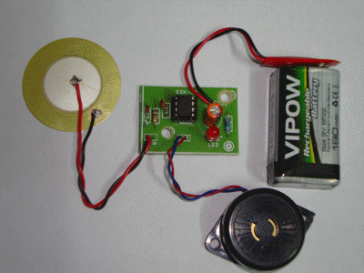
The circuit uses a Piezo element (one used in Buzzer) as the heat sensor. The piezo crystals reorient when subjected to heat or mechanical stress and generates about one volt through the Direct piezoelectric property. IC1 is designed as a voltage sensor with both the inputs tied through the capacitor C1.The non inverting input is connected to the ground through R1 to keep the output low in the standby state. The inputs of IC1 are very sensitive and even a minute change in voltage level will change the output state.
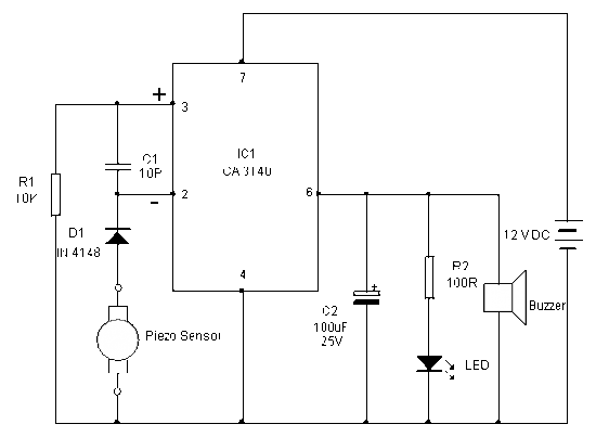
In the standby mode, both the inputs of IC1 are balanced so that output remains low. When the Piezo element accepts heat, it generates a minute voltage which will upset the input balance and output swings high. This triggers LED and Buzzer. Capacitor C2 gives a short lag before the buzzer beeps to avoid false triggering. Warning beep continues till the piezo element cools.
Note: Enclose the circuit inside the PC with the piezo element close to the heat sink of the processor. Adjust the distance between the piezo element and heat sink so as to keep the circuit standby in the normal condition. The piezo element can sense a 10 degree rise in temperature from a distance of 5 cms. Power to the circuit can be tapped from the 12 volt line of SMPS.
Sourced by Dr. Mohn kumar
Sourced by Dr. Mohn kumar

Tuesday, August 26, 2014
Simple Heat Sensor Wiring diagram Schematic
This simple heat sensor schema could senses heat from various electronics device like computer, amplifier etc. and generate warning alarm. It could senses heat from environment also, but here I mention “electronics device” because it is being using mostly in electronic device to protect them from overheat.
Thermistor, 110 Ohms:
| Fig-2: 110 Ohms Thermistor |
As it is a heat sensor schema, here a thermistor is used as a heat sensor. It is a thermal measurement device and has a variety of usages including temperature sensor/ heat sensor. The thermistor used in this schema is a NTC (Negative Temperature Coefficient) type thermistor. When temperature increases, its resistance goes decrease. Therefore, NTC thermistor’s resistances are inverse of temperature.
Circuit Description:
You have seen, in this simple schema diagram of heat sensor, a few number of components is used including a BC548 transistor, a 110 ohms thermistor etc.- BC548: BC548 is a TO-92 type NPN transistor, as its alternative you can use 2N2222, BC238, BC548, BC168, BC183 etc. they all have almost same characteristic.
- 110 Ohms Thermistor: A 110 Ohms thermistor is used to detecting heat. I have told already about it.
- Buzzer: A buzzer is used with +9V and collector of transistor. When the temperature/ heat exceeds a certain level then it make an alarm.
- 4.7V Zener diode: It is used to limit the emitter current of BC548.
- 9V Battery: A 9V battery is used as a single power source.
- R1, R2: A 3.3K 1/4w resistor is used as R1 and 100 ohms 1/4w as R2.
- Switch: Here in this schema the switch used is a simple SPST switch. You can either use the switch or not, choice is yours. It is not mandatory.
Subscribe to:
Posts (Atom)