Showing posts with label controller. Show all posts

Sunday, October 26, 2014

Water Pump Relay Controller Circuit Schematic

By means of a Relay, employed to drive a water pump, this circuit provides automatic level control of a water reservoir or well. The shorter steel rod is the "water high" sensor, whereas the longer is the "water low" sensor. When the water level is below both sensors, IC1C output (pin #10) is low; if the water becomes in contact with the longer sensor the output remains low until the shorter sensor is reached. At this point IC1C output goes high, Q1 conducts, the Relay is energized and the pump starts operating.

Now, the water level begins to decrease and the shorter sensor will be no longer in contact with the water, but IC1C output will be hold high by the signal return to pin #5 of IC1B, so the pump will continue its operation. But when the water level falls below the longer sensor, IC1C output goes low and the pump will stop. SW1 is optional and was added to provide reverse operation. Switching SW1 in order to connect R3 to pin #11 of IC1D, the pump will operate when the reservoir is nearly empty and will stop when the reservoir is full. In this case, the pump will be used to fill the reservoir and not to empty it as in the default operating mode.


Circuit diagram:
 water pump relay control schematic circuit diagram
Water Pump Relay Control Circuit Diagram


Parts:

R1 = 15K - 1/4W Resistors
R2 = 15K - 1/4W Resistors
R3 = 10K - 1/4W Resistor
R4 = 1K - 1/4W Resistor
D1 = LED - any type and color
D2 = 1N4148 - 75V 150mA Diode
Q1 = BC337 - 45V 800mA NPN Transistor
IC1 = 4001 Quad 2 Input NOR Gate CMos IC
SW = SPDT Toggle or Slide Switch (Optional)
RL1 = Relay with SPDT 2A @ 230V switch
Coil Voltage 12V - Coil resistance 200-300 Ohm
Two steel rods of appropriate length


Notes:
  • The two steel rods must be supported by a small insulated (wooden or plastic) board.
  • The circuit can be used also with non-metal tanks, provided a third steel rod having about the same height of the tank will be added and connected to the circuits negative ground.
Read More..

Saturday, October 25, 2014

Simple DC Fan Controller

This circuit is ideal to control the cooling fan of heat generated electronic gadgets like power amplifiers. The circuit switches on a fan if it senses a temperature above the set level. The fan automatically turns off when the temperature returns to normal.

The circuit uses an NTC (Negative Temperature Coefficient) Thermister to sense heat. NTC Thermister reduces its resistance when the temperature in its vicinity increases.IC1 is used as a voltage comparator with two potential dividers in its inputs. Resistor R1 and VR1 forms one potential divider connected to the non inverting input of IC1 and another potential divider comprising R2 and the 4.7K Thermister supplying a variable voltage to the inverting input of IC1. VR1 is adjusted so as to give slightly lesser voltage at the non inverting input than the inverting input at room temperature.

DC Fan Controller Circuit

In this state, output of IC1 will be low and the Fan remains off. When the temperature near the Thermister increases, its resistance decreases and conducts. This drops the voltage at pin 2 of IC1 and its output becomes high. T1 then triggers and fan turn on. Red LED indicates that fan is running. Capacitor C1 gives a short lag before T1 turns on to avoid false triggering and to give proper bias to T1.DC fan can be the one used in Computer SMPS.

Keep the Thermistor near the heat sink of the Amplifier PCB and switch on the amplifier for 10 minutes. Then adjust VR1 till the Fan stop running.When the temperature rises, Fan will automatically switch on. 
 
 
Sourced by : Link
Read More..

Wednesday, October 22, 2014

Water Level Controller Detector

Water Level Controller Detector. In most houses, water is first stored in an underground tank (UGT) and from there it is pumped up to the overhead tank (OHT) located on the roof. People generally switch on the pump when their taps go dry and switch off the pump when the overhead tank starts overflowing. This results in the unnecessary wastage and sometimes non-availability of water in the case of emergency.  The simple circuit presented here makes this system automatic, i.e. it switches on the pump when the water level in the overhead tank goes low and switches it off as soon as the water level reaches a pre-determined level. It also prevents ‘dry run’ of the pump in case the level in the underground tank goes below the suction level. 

  Water Level Contoroller Circuit diagram
In the figure, the common probes connecting the underground tank and the overhead tank to +9V supply are marked ‘C’. The other probe in underground tank, which is slightly above the ‘dry run’ level, is marked ‘S’. The low-level and high-level probes in the overhead tank are marked ‘L’ and ‘H’, respectively.  When there is enough water in the underground tank, probes C and S are connected through water.As a result,transistor T1 gets forward biased and starts conducting. This, in turn, switches transistor T2 on. 

Initially, when the overhead tank is empty, transistors T3 and T5 are in cut-off state and hence pnp transistors T4 and T6 get forward biased via resistors R5 and R6, respectively.  As all series-connected transistors T2, T4, and T6 are forward biased, they conduct to energise relay RL1 (which is also connected in series with transistors T2, T4, and T6). Thus the supply to the pump motor gets completed via the lower set of relay contacts (assuming that switch S2 is on) and the pump starts filling the overhead tank. 

Water Level Contoroller Tank Circuit

Once the relay has energised, transistor T6 is bypassed via the upper set of contacts of the relay. As soon as the water level touches probe L in the overhead tank, transistor T5 gets forward biased and starts conducting. This, in turn, reverse biases transistor T6, which then cuts off. But since transistor T6 is bypassed through the relay contacts, the pump continues to run. The level of water continues to rise.  When the water level touches probe H, transistor T3 gets forward biased and starts conducting. This causes reverse biasing of transistor T4 and it gets cut off. As a result, the relay de-energises and the pump stops. Transistors T4 and T6 will be turned on again only when the water level drops below the position of L probe. 

Presets VR1, VR2, and VR3 are to be adjusted in such a way that transistors T1, T3, and T5 are turned on when the water level touches probe pairs C-S, C-H, and C-L, respectively. Resistor R4 ensures that transistor T2 is ‘off’ in the absence of any base voltage. Similarly, resistors R5 and R6 ensure that transistors T4 and T6 are ‘on’ in the absence of any base voltage. Switches S1 and S2 can be used to switch on and switch off, respectively, the pump manually.  You can make and install probes on your own as per the requirement and facilities available. However, we are describing here how the probes were made for this prototype. 

The author used a piece of non-metallic conduit pipe (generally used for domestic wiring) slightly longer than the depth of the overhead tank. The common wire C goes up to the end of the pipe through the conduit. The wire for probes L and H goes along with the conduit from the outside and enters the conduit through two small holes bored into it as shown in Fig. 2. Care has to be taken to ensure that probes H and L do not touch wire C directly. Insulation of wires is to be removed from the points shown. The same arrangement can be followed for the underground tank also. To avoid any false triggering due to interference, a shielded wire may be used.
Read More..

Monday, October 20, 2014

Junk box Fan Speed Controller

My new home theatre receiver was getting rather hot in the close confines of its cabinet, with the temperature reaching over 40°C after only about 30 minutes of use. To help lower the temperature, I decided to install a fan in the cabinet. A 75mm hole was cut in the shelf under the receiver, and a 12V fan salvaged from an old computer power supply was mounted underneath. The fan was powered from a 12V DC plugpack. 

This did the job, keeping the temperature below 30°C even after prolonged use on a warm day. However, the fan was annoyingly loud when running at full speed. To reduce the noise level substantially, I built this fan speed controller with temperature feedback. The circuit was culled from variety of ideas found on various sites on the internet, with the final circuit designed from what was in the "junk box". Air temperature in the cabinet is sensed via an LM335 (TS1).

Circuit diagram:
junk-box-fan-speed-controller circuit diagram
Junk-box Fan Speed Controller Circuit Diagram

It is glued to a piece of aluminium about 25mm square with instant glue, which is then attached to the top of the receiver with "Blue-Tack". About 300mm of audio coax makes the connection back to the circuit board. The LM335’s output rises 10mV per degree Centigrade. It is calibrated to zero output at -273°C, so at 20°C, the output will be 2.93V. This is applied to the non-inverting input of a 741 op amp (IC1). A 1N4733 5.1V Zener diode provides a voltage reference for the inverting input via trimpot VR1. The output of the op amp drives a TIP122 Darlington transistor (Q1), which in turn drives the fan motor. The op amp gain was calculated to give about 12V to the fan at 40°C. 
 
To keep the transistor cool, it is mounted on the metal base of a small plastic box, which is also used to house the components.  Initial setup should be performed with everything turned off and the ambient temperature at about 20°C. Adjust the 10-turn pot until the fan just stops running. I used a gasket made from foam strips and "blue-tacked" them between the feet of the receiver to direct all of the airflow through it. The temperature now remains at about 32°C, the fan runs very quietly and continues to run down for about 30 minutes after the receiver is switched off.


Author: Martin Cook - Copyright: Silicon Chip Electronics
Read More..

Under floor Heating Controller Circuit Diagram

Central heating systems that include under-floor heating of ten leave the extra pump used to pump the water through the under-floor pipes running continuously. The reason for this is that the central heating controller doesn’t have a separate control circuit and output for the underfloor heating pump.

Under-floor Heating Controller Circuit Diagram


This circuit was designed to control the under-floor heating pump independently or via the switch in the living room thermostat. The design has been made very flexible and can be connected in four different ways:
  1. Temperature sensor 1 is connected to the inlet pipe of the under floor heating, Temperature sensor 2 is shor ted. The pump is turned on when the inlet pipe becomes warm enough. When the temperature of the inlet pipe drops below the trigger temperature the pump will continue to run for 20 minutes.
  2. Temperature sensor 1 is connected to the inlet pipe of the underfloor heating, Temperature sensor 2 is connected to the outlet pipe. This works in a similar way to that in the previous configuration, but also: as long as the inlet pipe is warm the pump will be stopped (temporarily) when the outlet pipe rises above the trigger temperature.
  3. Switch input connected to the living room thermostat. As long as the switch (connected to the same input as for Temperature sensor 1) is closed, the pump will run. When the switch opens the pump stops after 20 minutes.
  4. Switch input connected to the living room thermostat, Temperature sensor 2 is connected to the outlet pipe of the underfloor heating. This works in a similar way to that in the previous configuration, but also: as long as the inlet pipe is warm the pump will be stopped (temporarily) when the outlet pipe rises above the trigger temperature.
Temperature sensor 2 can also be used to protect the underfloor heating from overheating. In this case, set the trigger temperature to about 50 degrees and connect the sensor to the inlet pipe of the pump.

The circuit is built around an ATtiny25. Two ADC inputs of the controller measure the voltage across both PTCs. The voltage across the first temperature sensor is compared by the software to a trigger value and zero. When the trigger value is exceeded or the value is zero (due to an external switch), the Motor power pin (pin 5) is pulled high and the pump is started via the optotriac. When the pump is started, another output (pin 6) is pulled low at the same time. You can connect external components to this output, such as an indicator lamp.

To prevent a continuous current from flowing through the presets and temperature sensors, the PTCs are connected to ground via a software-controlled FET only when a measurement is made.

A configuration fuse inside the microcontrol-ler is blown so that the internal clock runs at 128 kHz. This is fast enough to run the pro-gram and this frequency is divided by 1024 in the prescaler of timer1. Timer1 then counts to 125 and generates an interrupt. This interrupt will occur approximately once per second.

During the interrupt routine the state for the pump is determined. When Temperature sen-sor 1 exceeds the trigger value or equals zero (switch input), the pump timer will be set to 20 minutes. These 20 minutes are to make sure that the pump remains on for another 20 minutes after the temperature has fallen below the trigger level. If the second temper-ature sensor goes above the trigger level the pump will be stopped immediately.

At the end of the interrupt routine a measure-ment is started by first making the FET con-duct so the PTCs are connected to ground. An ADC routine is then run to read in the value. The temperature sensors are measured alter-nately, so that the measurement interval for each sensor is 2 seconds.

The circuit will turn on the pump for a mini-mum of 5 minutes during any 18-hour period. For this there is a Summer-timer, which keeps track of how long ago the pump was last on. When the pump is turned on the Summer-timer is reset to zero. If the Summer-timer hasn’t been reset for 18 hours (16-bit integer = 65,536 s = 18.2 hours), the pump timer will be set to 5 minutes. As long as this is active, the pump will be on.

Author: Marc Dirix - Copyright: Elektor
Read More..

Saturday, September 13, 2014

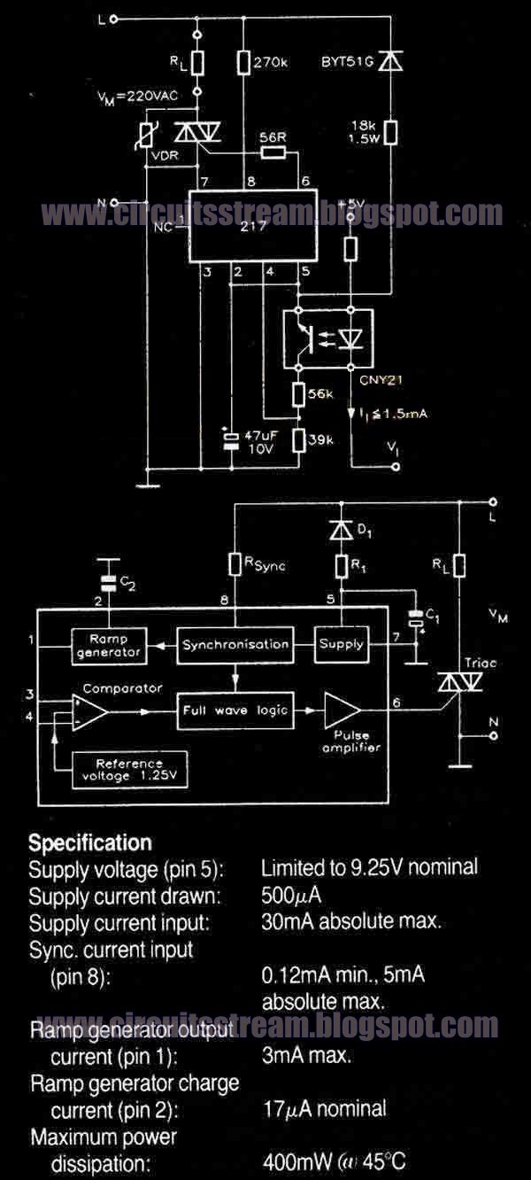
Temperature Controller Wiring diagram Schematic with U217B

This is a simple Temperature Controller Circuit Diagram with U217B. A triac controller for switching resistive loads directly from the mains supply using the zero crossing technique. The device is powered directly from the mains via a diode and dropper resistor, and the IC has its own regulator to limit its supply to 9.25V. 

 Temperature Controller Circuit Diagram with U217B 


 temperature controller circuit diagram with u217b


To ensure that no switching occurs outside of the zero crossing point, full wave logic is employed to guarantee that complete mains cycles only are switched to the load. A ramp a freely selectable ramp duration (as determined by a timing capacitor),together with the full-wave logic block, synchronised to the AC supply at pin 8 via a dropper resistor (RSync). The ramp generator not only provides symmetrical trigger pulse c .


Read More..

Friday, September 5, 2014

Intelligent Water Pump Controller with Water level Display

Most of the diagram for multi-level indication/control of water in tanks employ a bunch of wires running between the schema and the overhead tank, which accounts for almost half the cost of the entire project. Here is an intelligent scanned water-level indicator-cum-pump controller schema (Fig. 1) that utilises just four wires to the overhead tank to indicate nine different levels. The connection arrangement for the overhead tank (OHT) and the underground tank (UGT) is shown in Fig. 2. Two wires from the schema in Fig. 1 run to the underground/ground-level tank (to output line K and return line J, respectively) to check the availability of water in the tank before operating the pump, thereby guarding the pump against the damage due to dry running.

Intelligent

Fig. 1: Intelligent water-level indicator-cum-water pump controller

The scanning section employs an NE555 timer (IC1) wired as an astable multivibrator to oscillate at around 1 kHz. The output of NE555 is connected to CLK inputs of two CD4017 Johnson counters (IC2 and IC8). (IC8 is placed near the overhead tank in Fig. 2.)

Suppose at a given time, there is some specific water level in the OHT. The clock from NE555 keeps advancing the Q outputs of IC2 and IC8 starting from Q0. Only when the Q output of IC8 corresponding to the first (starting from top) water-submerged probe goes high, the OHT RET line goes high through water in the OHT. This causes pins 2, 5, 10, and 13 of quad AND gate ICs (IC3 and IC4) as well as one input of AND gate A2 to go high via emitter-follower transistor T2. The identical Q output of IC2 goes high simultaneously to light up the corresponding LED (LED1 through LED9) to indicate that particular level.

Connection

Fig. 2: Connection arrangement for overhead and underground tanks

Similarly, upon reception of the next clock, the next lower level is indicated by the next LED, and so on. Scanning at a very high speed gives the illusion that all LEDs up to the one corresponding to the actual level in the OHT are continuously lit. This is due to the persistence of vision.

When the water level in the OHT is high enough to light up LED1, both the inputs of AND gate A1 also go high simultaneously. As a result, the output of AND gate A1 goes high to reset the flip-flop IC (IC5). The output pin 2 of IC5 goes low to de-energise relay RL1. Now when the water level in the OHT goes low such that LEDs 1 through 9 are off, the output of AND gate A3 goes high to set RS flip-flop (IC5), thereby making its output pin 2 high. Only when there is enough water in the UGT, pin 12 of AND gate A4 will be at logic 1 to provide forward bias to relay driver transistor SL100 (T3) to energise the relay to switch on the pump motor. The motor will switch off only when the water level reaches the uppermost level or when the UGT gets empty. LED10 through LED12 indicate ‘motor off’, ‘motor on’, and ‘UGT empty’, respectively. IC8 is powered separately, using a 9V battery that lasts long enough.

This schema costs around Rs 200.


 Sourced By: EFY: Author : Johnson Mathew Easow
Read More..

SMS Remote controller circuit

SMS Remote controller is a device used to control a device remotely using SMS through GSM mobile phones. Process control equipment with a series of AVR ATTiny To SMS Remote Controller can be used to control life and death of these equipment will provide information on the status of replies to our phone in return successful command execution. 
Equipment can be controlled by a series of AVR ATTiny To SMS Remote Controller include lights, water pumps, garage doors, gates and much more. AVR series ATTiny To SMS Remote controller uses the module-47 Sony ericson GM as recipient and sender of the SMS module. Then to the SMS data processor on a series of AVR ATTiny To SMS Remote controller is using AVR microcontroller ATTiny 2313.


Series AVR ATTiny To SMS Remote Controller

SMS Remote controller circuit Click to view larger. 

AVR circuit this part ATTiny To SMS Remote Controller
AVR series ATTiny To SMS Remote controller uses the AVR attiny2313 with 4MHz clock frequency, GSM Module GM trnceiver 47 Sony ericson, SIM Card, 4 relays and an IC regulator. ATTiny AVR microcontroller 2313 can work well on the voltage 2.7 VDC - 5.5 VDC for working with the frequency at 10MHz bahwah. 

The set of AVR ATTiny In SMS Remote Controller To make use of this power supply from the batteries 3.3 VDC. Connection using a SIM Card SIM Card Holder which is connected to the module GM-47, AVR series ATTiny To SMS Remote Controller works with communication between AVR ATTiny and GM-47 module at 9600bps. In a series of AVR ATTiny To SMS Remote controller is equipped with LED D6 as an indicator of the data interconnect GM-47 module with cellular operators where this LED will light continuously when not apat network and will be lit by flashes when a signal from the operator.

Specifications AVR series ATTiny To SMS Remote Controller


  • 4 Relay for ON / OFF electronic devices
  • 8 input lines for reading in a normal switching
  • LED indicators signal operator
  • SMS command with password, so only the owner can operate
Read More..

Sunday, August 24, 2014

Kitchen Exhaustion Fan Controller

Exhaustion fan is a very important element in kitchens. Here may be a easy schema to manage kitchen fans by monitoring the ambient temperature. its engineered round the renowned precision integrated temperature sensor chip LM35 (IC1). remainder of the schema may be a non-traditional electromagnetic relay driver wired round the fashionable LED driver LM3914 (IC2). User will switch 3 presetted temperature levels employing a jumper/slide switch (JP1), that determines the warmth level to activate the relay and hence the electrical exhaustion fan wired through the relay contacts. It works off 12V DC power offer.

Kitchen Exhaustion Fan Controller  Circuit Schematic


Only one adjustment is needed during this kitchen Exhaustion fan controller schema. when construction, set jumper purpose in its 1st position, ie base terminal of T1 is connected to pin thirteen of IC2 and alter the preset P1 fastidiously in order that relay RL1 is energised when ambient temperature level reaches close to 29oC. but this is often not terribly vital as youll choose any threshold level by connecting the jumper points to alternative unused output pins of IC2 (here solely three outputs are used).
Read More..

Friday, August 15, 2014

Under floor Heating Controller Wiring diagram Schematic

Central heating systems that include under-floor heating of ten leave the extra pump used to pump the water through the under-floor pipes running continuously. The reason for this is that the central heating controller doesn’t have a separate control schema and output for the underfloor heating pump.

Under-floor Heating Controller Circuit Diagram


This schema was designed to control the under-floor heating pump independently or via the switch in the living room thermostat. The design has been made very flexible and can be connected in four different ways:
  1. Temperature sensor 1 is connected to the inlet pipe of the under floor heating, Temperature sensor 2 is shor ted. The pump is turned on when the inlet pipe becomes warm enough. When the temperature of the inlet pipe drops below the trigger temperature the pump will continue to run for 20 minutes.
  2. Temperature sensor 1 is connected to the inlet pipe of the underfloor heating, Temperature sensor 2 is connected to the outlet pipe. This works in a similar way to that in the previous configuration, but also: as long as the inlet pipe is warm the pump will be stopped (temporarily) when the outlet pipe rises above the trigger temperature.
  3. Switch input connected to the living room thermostat. As long as the switch (connected to the same input as for Temperature sensor 1) is closed, the pump will run. When the switch opens the pump stops after 20 minutes.
  4. Switch input connected to the living room thermostat, Temperature sensor 2 is connected to the outlet pipe of the underfloor heating. This works in a similar way to that in the previous configuration, but also: as long as the inlet pipe is warm the pump will be stopped (temporarily) when the outlet pipe rises above the trigger temperature.
Temperature sensor 2 can also be used to protect the underfloor heating from overheating. In this case, set the trigger temperature to about 50 degrees and connect the sensor to the inlet pipe of the pump.

The schema is built around an ATtiny25. Two ADC inputs of the controller measure the voltage across both PTCs. The voltage across the first temperature sensor is compared by the software to a trigger value and zero. When the trigger value is exceeded or the value is zero (due to an external switch), the Motor power pin (pin 5) is pulled high and the pump is started via the optotriac. When the pump is started, another output (pin 6) is pulled low at the same time. You can connect external components to this output, such as an indicator lamp.

To prevent a continuous current from flowing through the presets and temperature sensors, the PTCs are connected to ground via a software-controlled FET only when a measurement is made.

A configuration fuse inside the microcontrol-ler is blown so that the internal clock runs at 128 kHz. This is fast enough to run the pro-gram and this frequency is divided by 1024 in the prescaler of timer1. Timer1 then counts to 125 and generates an interrupt. This interrupt will occur approximately once per second.

During the interrupt routine the state for the pump is determined. When Temperature sen-sor 1 exceeds the trigger value or equals zero (switch input), the pump timer will be set to 20 minutes. These 20 minutes are to make sure that the pump remains on for another 20 minutes after the temperature has fallen below the trigger level. If the second temper-ature sensor goes above the trigger level the pump will be stopped immediately.

At the end of the interrupt routine a measure-ment is started by first making the FET con-duct so the PTCs are connected to ground. An ADC routine is then run to read in the value. The temperature sensors are measured alter-nately, so that the measurement interval for each sensor is 2 seconds.

The schema will turn on the pump for a mini-mum of 5 minutes during any 18-hour period. For this there is a Summer-timer, which keeps track of how long ago the pump was last on. When the pump is turned on the Summer-timer is reset to zero. If the Summer-timer hasn’t been reset for 18 hours (16-bit integer = 65,536 s = 18.2 hours), the pump timer will be set to 5 minutes. As long as this is active, the pump will be on.


Author: Marc Dirix - Copyright: Elektor
Read More..