Showing posts with label fan. Show all posts

Tuesday, November 18, 2014

DC fan control circuit for power amplifier

DC fan control circuit for power amplifier .Variable speed DC fanThis series of works based on the input signal. Speed ​​/ fan rotation depending on size of the input signal coming from speaker lines. If there is no signal then the fan will spin slowly according to the setting VR1.Input supply can be taken directly from the main transformer power amplifier, 12V CT 12V, so no need to increase the transformer again.
Circuit Schematic Electronics | CSE

This circuit has been tested and do not cause buzzing.correction: the lowest R: 560 ohm
Read More..

Saturday, October 25, 2014

Simple DC Fan Controller

This circuit is ideal to control the cooling fan of heat generated electronic gadgets like power amplifiers. The circuit switches on a fan if it senses a temperature above the set level. The fan automatically turns off when the temperature returns to normal.

The circuit uses an NTC (Negative Temperature Coefficient) Thermister to sense heat. NTC Thermister reduces its resistance when the temperature in its vicinity increases.IC1 is used as a voltage comparator with two potential dividers in its inputs. Resistor R1 and VR1 forms one potential divider connected to the non inverting input of IC1 and another potential divider comprising R2 and the 4.7K Thermister supplying a variable voltage to the inverting input of IC1. VR1 is adjusted so as to give slightly lesser voltage at the non inverting input than the inverting input at room temperature.

DC Fan Controller Circuit

In this state, output of IC1 will be low and the Fan remains off. When the temperature near the Thermister increases, its resistance decreases and conducts. This drops the voltage at pin 2 of IC1 and its output becomes high. T1 then triggers and fan turn on. Red LED indicates that fan is running. Capacitor C1 gives a short lag before T1 turns on to avoid false triggering and to give proper bias to T1.DC fan can be the one used in Computer SMPS.

Keep the Thermistor near the heat sink of the Amplifier PCB and switch on the amplifier for 10 minutes. Then adjust VR1 till the Fan stop running.When the temperature rises, Fan will automatically switch on. 
 
 
Sourced by : Link
Read More..

Thursday, October 23, 2014

Improvised Fan Grills

Making your own grill for your fans would be a lot easier and cheaper. You could use all materials that can be found in your home.

Hacks and Mods: Improvised Fan Grills

Your main component would be your old fan, removed its metal ring and you can now measure the desired length or size of grid that you will be needed. Cut the grid across so it will be easier to cut, then place it in the tower and use the same screw you removed in the fan.

Hacks and Mods: Improvised Fan Grills

Now you can put the grid holding fan back in its place. Clean up and you can now use your very own fan grills that cost almost nothing but your patience.
Read More..

Monday, October 20, 2014

Junk box Fan Speed Controller

My new home theatre receiver was getting rather hot in the close confines of its cabinet, with the temperature reaching over 40°C after only about 30 minutes of use. To help lower the temperature, I decided to install a fan in the cabinet. A 75mm hole was cut in the shelf under the receiver, and a 12V fan salvaged from an old computer power supply was mounted underneath. The fan was powered from a 12V DC plugpack. 

This did the job, keeping the temperature below 30°C even after prolonged use on a warm day. However, the fan was annoyingly loud when running at full speed. To reduce the noise level substantially, I built this fan speed controller with temperature feedback. The circuit was culled from variety of ideas found on various sites on the internet, with the final circuit designed from what was in the "junk box". Air temperature in the cabinet is sensed via an LM335 (TS1).

Circuit diagram:
junk-box-fan-speed-controller circuit diagram
Junk-box Fan Speed Controller Circuit Diagram

It is glued to a piece of aluminium about 25mm square with instant glue, which is then attached to the top of the receiver with "Blue-Tack". About 300mm of audio coax makes the connection back to the circuit board. The LM335’s output rises 10mV per degree Centigrade. It is calibrated to zero output at -273°C, so at 20°C, the output will be 2.93V. This is applied to the non-inverting input of a 741 op amp (IC1). A 1N4733 5.1V Zener diode provides a voltage reference for the inverting input via trimpot VR1. The output of the op amp drives a TIP122 Darlington transistor (Q1), which in turn drives the fan motor. The op amp gain was calculated to give about 12V to the fan at 40°C. 
 
To keep the transistor cool, it is mounted on the metal base of a small plastic box, which is also used to house the components.  Initial setup should be performed with everything turned off and the ambient temperature at about 20°C. Adjust the 10-turn pot until the fan just stops running. I used a gasket made from foam strips and "blue-tacked" them between the feet of the receiver to direct all of the airflow through it. The temperature now remains at about 32°C, the fan runs very quietly and continues to run down for about 30 minutes after the receiver is switched off.


Author: Martin Cook - Copyright: Silicon Chip Electronics
Read More..

Wednesday, September 24, 2014

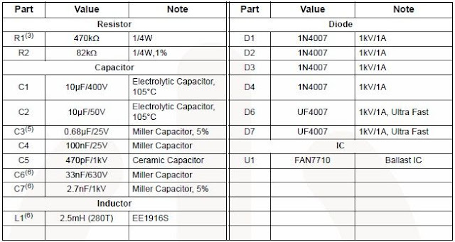
Simple FAN 7710 Ballast Control

Using the FAN 7710 Ballast Control IC for Compact Fluorescent Lamps developed using Fairchild’s unique highvoltage process and system-in-package (SiP) concept can be designed a very simple low cost fluorescent lamp driver electronic project .The FAN7710 ballast control controls internal high-voltage stress and delivers 20W to the lamp at 320VDC voltage.

FAN7710 ballast control incorporates a preheating /ignition function, controlled by an user-selected external capacitor, to increase lamp life. The FAN7710 detects switch operation from after ignition-mode through an internal active Zero-Voltage Switching (ZVS) control circuit.


The AC line input voltage (230 VAC 50 Hz) is rectified to provide a bus voltage of approximately 320 volts DC. Startup resistor R1 supplies initial power to the FAN7710 IC.The IC begins to oscillate and the charge pump circuit consisting of C2, D2 and D7 supplies the current to the VDD pin, which gets regulated through the internal 15-V shunt regulator.

FAN7710 Ballast Control
Read More..

Friday, August 29, 2014

Temperature controlled Fan

This schema adopt a rather old design technique as its purpose is to vary the speed of a fan related to temperature with a minimum parts counting and avoiding the use of special-purpose ICs, often difficult to obtain.


Temperature-controlled


Parts:


P1_____________22K Linear Potentiometer (See Notes)

R1_____________15K @ 20°C n.t.c. Thermistor (See Notes)
R2____________100K 1/4W Resistor
R3,R6__________10K 1/4W Resistors
R4,R5__________22K 1/4W Resistors
R7____________100R 1/4W Resistor
R8____________470R 1/4W Resistor
R9_____________33K 4W Resistor

C1_____________10nF 63V Polyester Capacitor

D1________BZX79C18 18V 500mW Zener Diode
D2_________TIC106D 400V 5A SCR
D3-D6_______1N4007 1000V 1A Diodes

Q1,Q2________BC327 45V 800mA PNP Transistors
Q3___________BC337 45V 800mA NPN Transistor

SK1__________Female Mains socket

PL1__________Male Mains plug & cable


R3-R4 and P1-R1 are wired as a Wheatstone bridge in which R3-R4 generate a fixed two-thirds-supply "reference" voltage, P1-R1 generate a temperature-sensitive "variable" voltage, and Q1 is used as a bridge balance detector.
P1 is adjusted so that the "reference" and "variable" voltages are equal at a temperature just below the required trigger value, and under this condition Q1 Base and Emitter are at equal voltages and Q1 is cut off. When the R1 temperature goes above this "balance" value the P1-R1 voltage falls below the "reference" value, so Q1 becomes forward biased, pulse-charging C1.
This occurs because the whole schema is supplied by a 100Hz half-wave voltage obtained from mains supply by means of D3-D6 diode bridge without a smoothing capacitor and fixed to 18V by R9 and Zener diode D1. Therefore the 18V supply of the schema is not true DC but has a rather trapezoidal shape. C1 provides a variable phase-delay pulse-train related to temperature and synchronous with the mains supply "zero voltage" point of each half cycle, thus producing minimal switching RFI from the SCR. Q2 and Q3 form a trigger device, generating a short pulse suitable to drive the SCR.


Notes:

* The schema is designed for 230Vac operation. If your ac mains is rated at about 115V, you can change R9 value to 15K 2W. No other changes are required.
* Circuit operation can be reversed, i.e. the fan increases its speed as temperature decreases, by simply transposing R1 and P1 positions. This mode of operation is useful in controlling a hot air flux, e.g. using heaters.
* Thermistor value is not critical: I tried also 10K and 22K with good results.
* In this schema, if R1 and Q1 are not mounted in the same environment, the precise trigger points are subject to slight variation with changes in Q1 temperature, due to the temperature dependence of its Base-Emitter junction characteristics. This schema is thus not suitable for use in precision applications, unless Q1 and R1 operate at equal temperatures.
* The temperature / speed-increase ratio can be varied changing C1 value. The lower the C1 value the steeper the temperature / speed-increase ratio curve and vice-versa.
* Warning! The schema is connected to 230Vac mains, then some parts in the schema board are subjected to lethal potential! Avoid touching the schema when plugged and enclose it in a plastic box.


Read More..

Sunday, August 24, 2014

Kitchen Exhaustion Fan Controller

Exhaustion fan is a very important element in kitchens. Here may be a easy schema to manage kitchen fans by monitoring the ambient temperature. its engineered round the renowned precision integrated temperature sensor chip LM35 (IC1). remainder of the schema may be a non-traditional electromagnetic relay driver wired round the fashionable LED driver LM3914 (IC2). User will switch 3 presetted temperature levels employing a jumper/slide switch (JP1), that determines the warmth level to activate the relay and hence the electrical exhaustion fan wired through the relay contacts. It works off 12V DC power offer.

Kitchen Exhaustion Fan Controller  Circuit Schematic


Only one adjustment is needed during this kitchen Exhaustion fan controller schema. when construction, set jumper purpose in its 1st position, ie base terminal of T1 is connected to pin thirteen of IC2 and alter the preset P1 fastidiously in order that relay RL1 is energised when ambient temperature level reaches close to 29oC. but this is often not terribly vital as youll choose any threshold level by connecting the jumper points to alternative unused output pins of IC2 (here solely three outputs are used).
Read More..