Showing posts with label temperature. Show all posts

Wednesday, October 29, 2014

Temperature Candle Using LED

LED based projects require a lot of skill and hence only experienced circuit designers try out these circuits. But there are also a few circuits in this genre that can be done by amateur electronic hobbyists. The temperature candle is one such circuit. Read on to know more about this.


The hardware components that are required to build this circuit are listed below:
  • Microcontroller
  • Temperature Sensor
  • RGB LED
  • PCB

The circuit design is pretty simple. The LED is made to flicker by the microcontroller and the color is based on the ambient temperature at that point. The temperature of the room can be known by observing the color of the LED.

The temperature value is obtained in degree Celsius. This value is received as a result of pressing the reset button on the PCB. This value can also be obtained by providing power to the device. Once the device is powered up, the change in temperature is indicated. The blue LED is triggered for a temperature increase of 10 degrees. The red LED is triggered for a temperature increase of a single degree.
Suppose, the ambient temperature is 23 degrees celsius, The circuit works in such a way that the blue LED is made to blink twice and the red LED is made to blink 3 times. Soon after this, an orange colored flicker is observed as the LED goes into canfle mode.

Since through hole components are used in this circuit, it is very cheap to construct and the components can be easily soldered. The circuit also contains a jack for connecting to a Microchip Pickit 3 programmer / debugger. This reduces the complexity involved in code modification and download.
Read More..

Saturday, October 25, 2014

Oil Temperature Gauge for 125 cc Scooter

Lots of Far-Eastern scooters are fitted with GY6 engines. These already elderly units are sturdy and economical, but if you want to  “push” the power a bit (so called ‘Racing’  kits, better handling of the advance, etc.), you soon find yourself faced with the problem  of the engine temperature, and it becomes essential to f it a heat sink (of ten wrongly  referred to as a ‘radiator’) on the oil circuit. Even so, in these circumstances, it’s more than reassuring for the user to have a constant clear indication of the oil temperature. Here are the specifications we set for the temperature gauge we wanted to build: 

Oil Temperature Gauge Circuit Diagram :
Oil Temperature Gauge-Circuit Diagram
  • no moving parts (so not meter movement), as scooters vibrate a lot!;
  • as cheap as possible (around £12);
  • robust measuring transducer (avoid NTC thermistors and other ‘exotic’ sensors);
  • temperature range 50–140 °C. (122 – 291 °F);
  • audible and visual warning in case of dangerous temperature;
  • compact;
  • waterproof.
Let’s start by the sensor. This is a type-K thermocouple, as regularly used by multimeter manufacturers. Readily available and fairly cheap, these are robust and have excellent linearity over the measurement range we’re interested in here. The range extends from 2 mV to 5.7 mV for ten measurement points. The positive output from the thermocouple is applied to the non-inverting input of IC3.A,  wired as a non-inverting amplifier. Its gain  of 221 is determined by R1 and R2. IC3 is an LM358, chosen for its favourable characteristics when run from a single-rail supply. IC3.B is wired as a follower, just to avoid leaving it powered with its pins floating. 

IC3.B output is connected to pin 5 of IC1, an LM3914. This very common IC is an LED display driver. We can choose ‘point’ or ‘bar’ mode operation, according to how pin 9 is connected. Connected as here to the + rail, the display will be in ‘bar’ mode. Pin 8, connected to ground, sets the full scale to 1.25 V. R3 sets the average LED current. Pin 4, via the potential divider R7/R8+R9, sets the offset  to 0.35 V. Using R8 and R9 in series like this avoids the need for precision resistors.

As per the LM3914 application sheet , R4-R5-R6 and C5 will make the whole display flash as soon as D10 lights (130 °C = 226 °F). Simultaneously, via R10 and T1, the (active) sounder will warn the user of overheating. Capacitor C6 avoids undesirable variations in the reference voltage in ‘flashing’ mode. IC2 is a conventional 7808 regulator and C1– C4 filter the supply rails. Do not leave these out! D1 protects the circuit against reverse polarity. 

The author has designed two PCBs to be fit-ted as a ‘sandwich’ (CAD file downloadable  from [1]). In the download you’ll also find  a document with a few photos of the project. You’ll note the ultimate weapon in on-board electronics: hot-melt glue. Better than epoxy (undoable!) and quite effective against vibration. 


Source by : ecicuits lab
Read More..

Saturday, September 13, 2014

Fire Alarm using NE555 and temperature sensor

Fire
This is a simple series of fire alarms. In this series used NE555 timer and temperature sensor to detect high temperatures. The working principle of this temperature sensor that is when the temperature is high around the sensor then there is resistance on the sensor to be small. 


However if the low temperature then the resistance will be high. If the resistance of small sensors, the voltage supply will be able to flow past the sensor and activate the transistor.


fire
IC1 NE555 as a regulator of the audio frequency. Transistors 1 and 2 are used as a driver IC1. Output (pin 3) of IC1 would trigger a transistor base T3 (SL100), which drives the speaker to produce sound the alarm. Frequency NE555 depending on resistance values ​​of R5 and R6 and the capacitance sensor C2 temperature. When the temperature gets hot, would provide a low resistance so that supply voltage can flow into the base of transistor T1 through a diode D1 and R2.

Capacitor C1 will charge a positive voltage so that it will increase the time when the fire alarm. The greater the value of C1, the greater the positive bias applied to the base of transistor T1 (BC548). T1 collector coupled to the base transistor T2, transistor T2 provides a positive voltage to pin 4 (reset) from IC1 (NE555). Resistors R4 will make IC1 NE555 continued to be active despite no positive voltage flowing.
Read More..

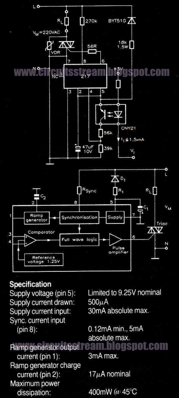
Temperature Controller Wiring diagram Schematic with U217B

This is a simple Temperature Controller Circuit Diagram with U217B. A triac controller for switching resistive loads directly from the mains supply using the zero crossing technique. The device is powered directly from the mains via a diode and dropper resistor, and the IC has its own regulator to limit its supply to 9.25V. 

 Temperature Controller Circuit Diagram with U217B 


 temperature controller circuit diagram with u217b


To ensure that no switching occurs outside of the zero crossing point, full wave logic is employed to guarantee that complete mains cycles only are switched to the load. A ramp a freely selectable ramp duration (as determined by a timing capacitor),together with the full-wave logic block, synchronised to the AC supply at pin 8 via a dropper resistor (RSync). The ramp generator not only provides symmetrical trigger pulse c .


Read More..

Friday, August 29, 2014

Temperature controlled Fan

This schema adopt a rather old design technique as its purpose is to vary the speed of a fan related to temperature with a minimum parts counting and avoiding the use of special-purpose ICs, often difficult to obtain.


Temperature-controlled


Parts:


P1_____________22K Linear Potentiometer (See Notes)

R1_____________15K @ 20°C n.t.c. Thermistor (See Notes)
R2____________100K 1/4W Resistor
R3,R6__________10K 1/4W Resistors
R4,R5__________22K 1/4W Resistors
R7____________100R 1/4W Resistor
R8____________470R 1/4W Resistor
R9_____________33K 4W Resistor

C1_____________10nF 63V Polyester Capacitor

D1________BZX79C18 18V 500mW Zener Diode
D2_________TIC106D 400V 5A SCR
D3-D6_______1N4007 1000V 1A Diodes

Q1,Q2________BC327 45V 800mA PNP Transistors
Q3___________BC337 45V 800mA NPN Transistor

SK1__________Female Mains socket

PL1__________Male Mains plug & cable


R3-R4 and P1-R1 are wired as a Wheatstone bridge in which R3-R4 generate a fixed two-thirds-supply "reference" voltage, P1-R1 generate a temperature-sensitive "variable" voltage, and Q1 is used as a bridge balance detector.
P1 is adjusted so that the "reference" and "variable" voltages are equal at a temperature just below the required trigger value, and under this condition Q1 Base and Emitter are at equal voltages and Q1 is cut off. When the R1 temperature goes above this "balance" value the P1-R1 voltage falls below the "reference" value, so Q1 becomes forward biased, pulse-charging C1.
This occurs because the whole schema is supplied by a 100Hz half-wave voltage obtained from mains supply by means of D3-D6 diode bridge without a smoothing capacitor and fixed to 18V by R9 and Zener diode D1. Therefore the 18V supply of the schema is not true DC but has a rather trapezoidal shape. C1 provides a variable phase-delay pulse-train related to temperature and synchronous with the mains supply "zero voltage" point of each half cycle, thus producing minimal switching RFI from the SCR. Q2 and Q3 form a trigger device, generating a short pulse suitable to drive the SCR.


Notes:

* The schema is designed for 230Vac operation. If your ac mains is rated at about 115V, you can change R9 value to 15K 2W. No other changes are required.
* Circuit operation can be reversed, i.e. the fan increases its speed as temperature decreases, by simply transposing R1 and P1 positions. This mode of operation is useful in controlling a hot air flux, e.g. using heaters.
* Thermistor value is not critical: I tried also 10K and 22K with good results.
* In this schema, if R1 and Q1 are not mounted in the same environment, the precise trigger points are subject to slight variation with changes in Q1 temperature, due to the temperature dependence of its Base-Emitter junction characteristics. This schema is thus not suitable for use in precision applications, unless Q1 and R1 operate at equal temperatures.
* The temperature / speed-increase ratio can be varied changing C1 value. The lower the C1 value the steeper the temperature / speed-increase ratio curve and vice-versa.
* Warning! The schema is connected to 230Vac mains, then some parts in the schema board are subjected to lethal potential! Avoid touching the schema when plugged and enclose it in a plastic box.


Read More..

Monday, August 18, 2014

Temperature To Frequency Converter Wiring diagram Schematic

This is a simple Temperature To Frequency Converter Circuit Diagram. enables the schema to be used as a reliable temperature-to- frequency converter; in combination with the fixed reference output of 1.00 V, offset scales. This In this schema an LM34 or LM35 produces a frequency proportional to temperature. Reference current (138 ) is set via R3. The output can be used to drive a display, frequency counter, or other indicating device for temperature readout.

Temperature To Frequency Converter Circuit Diagram


Temperature

Read More..

Friday, August 8, 2014

Temperature Monitor Wiring diagram Schematic

A simple op-amp schema that will trigger a relay when a preset temperature is reached. Please note that there is no hysteresis in this schema, so that if the temperature changes rapidly, then the relay may switch rapidly.

Temperature Monitor Circuit Diagram

Temperature-Monitor-Circuit-Diagram
Circuit Notes:
This schema uses an ordinary NTC thermistor with a resistance of 47k at room temperature. A suitable part from Maplin Electronics is FX42V. The schema is set in balance by adjusting the the 47k potentiometer. Any change in temperature will alter the balance of the schema, the output of the op-amp will change and energize the relay. Swapping the position of the thermistor and 47k resistor makes a cold or frost alarm.

Calibration:
At room temperature (25 degrees Celsius) a 47k NTC thermistor resistance is approximately 47k. The non-inverting op-amp input will then be roughly half the supply voltage, adjusting the 47k pot should allow the relay to close or remain open. To calibrate the device, the thermistor ideally needs to be at the required operating temperature. If this is for example, a hot water tank, then the resistance will decrease, one way to do this is use a multimeter on the resistance scale, read the thermistors resistance and then set the preset so that the schema triggers at this temperature.

Please note that if the temperature then falls, the relay will de-energize. If the environment temperatures changes rapidly, then the relay may chatter, as there is no hysteresis in this schema.

Hysteresis, allows a small amount of "backlash" to be tolerated. With a schema employing hysteresis, there will be no relay chatter and the schema will trigger at a defined temperature and require a different temperature to return to the normal state. Hysteresis can be applied to the schema using feedback, try a 1Meg resistor between op-amp output, pin 6 and the non-inverting input pin 2 to give the schema hysteresis.

Without offset null adjustment, the output of the 741 IC will be around 2 Volts (quiescent) swinging to nearly full supply when triggered. The 4.7k and 1k resistor form a potential divder so that under quiescent conditions the transistor will be off. Quiescent or steady state means no signal, or in this case (when the temperature does not cause the output to swing to full voltage) 
Read More..