Showing posts with label rf. Show all posts
Showing posts with label rf. Show all posts
Wednesday, November 5, 2014
High Level Wideband RF Preamplifier
This High Level Wideband RF Preamplifier can be made in two ways: (1) with the aid of a linear active element, or (2) with a non-linear element operating with negative feed-back. This circuit is of the second kind, using an RF power transistor as the active element. Feedback is also required to ensure correct termination (50 Q) of the aerial, since bipolar transistors normally exhibit a low input impedance. Also, the noise figure is not increased because virtually no signal is lost.
High Level Wideband RF Preamplifier Circuit Diagram:
![RF]()
The common-base amplifier is based on a UHF class A power transistor Type 2N5109 from Motorola. The feedback circuit is formed by RF transformer Th. The input and output impedance of the preamplifier is 50 4 for optimum perform-ance. Network R3-C5 may have to be added to preclude oscillation outside the pass-band, which ranges from about 100 kHz to 50 MHz. The gain is approximately 9.5 dB, the noise figure is between 2 and 3 dB, and the third-order output intercept point is at least 50 dBm.
The input/output transformer is wound on a Type FT37-75 ferrite core from Micrometals. The input winding is 1 turn, the output winding 5 turns with a tap at 3 turns.
High Level Wideband RF Preamplifier Circuit Diagram:
The input/output transformer is wound on a Type FT37-75 ferrite core from Micrometals. The input winding is 1 turn, the output winding 5 turns with a tap at 3 turns.

Saturday, October 25, 2014
RF Transmitter using LM317 Circuit Diagram
This is the simple RF Transmitter using LM317 Circuit Diagram. Already we saw that the LM317 has hundreds of utilities besides a voltage regulator, how in this article of a audio amplifier with the LM317. Now that circuit the LM317 works for transmit radio waves in CW. The transmitter was done by SM0VPO and works very well, only not found the description the coil.
RF Transmitter using LM317 Circuit Diagram

If you liked this article,Take a few Seconds to Share this and leave comments
RF Probe for Multimeter Circuit Diagram
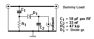
This is the RF Probe for Multimeter Circuit DiagramTo measure the RF voltage in a circuit to convert the signal unless they RF voltmeter. This conversion may be done with a very simple circuit, called a point or RF probe. A tip for RF Multimeter has to be made in a metal box with two connectors, one that receives the RF signal and another that goes to the multimeter.
In the case of this circuit the signal passes through two connectors between them and the RF signal is picked up.This signal passes through a 18 pF capacitor, a diode germanium, a resistor of 47 kOhm, and a bypass capacitor 33 nF. The anode of the diode is connected to the positive lead of the voltmeter and the other to ground.
RF Probe for Multimeter Circuit Diagram
Monday, August 25, 2014
RF Probe for Multimeter Wiring diagram Schematic
This is the RF Probe for Multimeter Circuit DiagramTo measure the RF voltage in a schema to convert the signal unless they RF voltmeter. This conversion may be done with a very simple schema, called a point or RF probe. A tip for RF Multimeter has to be made in a metal box with two connectors, one that receives the RF signal and another that goes to the multimeter.
In the case of this schema the signal passes through two connectors between them and the RF signal is picked up.This signal passes through a 18 pF capacitor, a diode germanium, a resistor of 47 kOhm, and a bypass capacitor 33 nF. The anode of the diode is connected to the positive lead of the voltmeter and the other to ground.
RF Probe for Multimeter Circuit Diagram
Subscribe to:
Posts (Atom)