Showing posts with label tda. Show all posts
Showing posts with label tda. Show all posts
Thursday, November 20, 2014
15W Stereo audio Amplifier using TDA 4935
TDA4935 2x15W audio amplifier is high quality Siemens IC. The IC can be used in stereo or bridge mode. In stereo mode can deliver 15W Stereo audio Amplifier using TDA 4935 per channel in bridge mode can deliver 30W to an 8 ohm load at the source of 30V. TDA4935 requires very few external components and has an ample supply voltage range. The IC operates in class B and has built-in protection circuits over temperature and overload protection.
Notes :
- The circuit must be assembled on a good quality PCB.
- TDA 4935 must be fitted with a proper heat sink.
- The supply voltage can be anything between 8 to 30V DC.
- Capacitors C1, C2, C8 are polyester capacitors.
- Capacitors C3, C4 and C6 are ceramic capacitors while C5 and C9 are electrolytic.

Wednesday, October 22, 2014
TDA 7309 Digital Audio Processor Circuit
Digital Audio Processor TDA 7309 is a stereo audio processor with independent volume control of each channel was to get the audio quality of a good processor. Digital Audio Processor TDA 7309 is equipped with a loudness control is controlled externally. Digital Audio Processor TDA 7309 also has a soft mute feature stand-alone for each canals. Digital Audio Processor TDA 7309 is controlled via the I2C serial bus system with a microcontroller interface.
Read More..
 |
| Click to view larger. |
Block Diagram of Digital Audio Processor TDA 7309 Feature-owned Digital Audio Processor TDA 7309 The input multiplexer with 3 stereo input Recording function on the output line Loudnes external ontrol Independent volume control Digital volume control with 1dB step Soft Mute All functions of the Digital Audio Processor TDA 7309 is programmed via the I2C serial bus system
Monday, October 20, 2014
Build a Single Chip FM Radio Circuit Diagram Using IC TDA 7000
To day i share cheapest cost FM radio circuit using IC TDA 7000. This Single Chip FM Radio Circuit Diagram is designed as per the data sheet and the result is excellent. Ideal for all category of electronic enthusiasts.
The TDA7000 is a monolithic integrated circuit for mono FM portable radios, where a minimum on peripheral components is crucial. The IC TDA 7000 has a Frequency-Locked-Loop system with an intermediate frequency of 70 kHz. The intermediate frequency selectivity is achieved by active RC filters. The only function which needs alignment is the resonant circuit for the oscillator, thus selecting the reception frequency. Spurious reception is avoided by means of a mute circuit, which also eliminates too noisy input signals. Special steps are taken to meet the radiation requirements.
Single Chip FM Radio Circuit Diagram Using IC TDA 7000
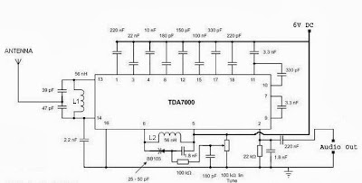
Notes
- For L1 and L2 wind 5 turns of 0.6 mm enameled Copper wire on a 4 mm dia plastic former.
- For antenna use a 50mm long insulated copper wire.
- IC TDA 7000 can withstand up to 10 V supply voltage.But I recommend 6V.
- Use an 8 Ohm speaker or Headphone at the audio output.
Thursday, September 18, 2014
Small Power Amplifier 8W 8Ω with TDA 2030
Although the TDA2030 can deliver 20 watts of output power, I deliberately reduced the output power to about 8 watts to supply 10 watt speakers. Input sensitivity is 200mV. Higher input levels naturally will give greater output, but no distortion should be heard. the gain is set by the 47k and 1.5k resistors. The TDA2030 IC is affordable and makes a good replacement amplifier for low to medium audio power systems. Incidentally, it is speaker efficiency that determines how "loud" your music is. Small Power Amplifier Circuit diagram: ![]() Parts:
Parts:
Read More..
R1-2=47ohmK 1/4W
R3= 1.5Kohm 1/4W
R4=1.2ohm /1W
C1-5=1uF/25V
C2-6=100uF/25V
C3-7=100nF/63V
C4=220nF/63V
D1-2=1N4001
IC1=TDA 2030
Friday, September 12, 2014
Small Power Amplifier 8W 8Ω with TDA 2030
Although the TDA2030 can deliver 20 watts of output power, I deliberately reduced the output power to about 8 watts to supply 10 watt speakers. Input sensitivity is 200mV. Higher input levels naturally will give greater output, but no distortion should be heard. the gain is set by the 47k and 1.5k resistors. The TDA2030 IC is affordable and makes a good replacement amplifier for low to medium audio power systems. Incidentally, it is speaker efficiency that determines how "loud" your music is. Small Power Amplifier Circuit diagram: ![]() Parts:
Parts:
Read More..
R1-2=47ohmK 1/4W
R3= 1.5Kohm 1/4W
R4=1.2ohm /1W
C1-5=1uF/25V
C2-6=100uF/25V
C3-7=100nF/63V
C4=220nF/63V
D1-2=1N4001
IC1=TDA 2030
Subscribe to:
Posts (Atom)