Wednesday, November 19, 2014
Surround Power Amplifier LM3886


Power Supply with tube
| Power Supply with tube |
Tuesday, November 18, 2014
Stereo Circuit Schematic of The ADAU1592 Audio Power Amplifier

DC fan control circuit for power amplifier
 |
| Circuit Schematic Electronics | CSE |
This circuit has been tested and do not cause buzzing.correction: the lowest R: 560 ohm
Monday, November 17, 2014
Protection of the Mosfet in flyback power supply
| Protection of the Mosfet in flyback power supply |
- Protection of the Mosfet in flyback power supply
- TRANSIL™ and blocking diode in a single package BENEFITS
- Accurate voltage clamping regardless load
- Reduced current loop
- Reduced EMI emission
- High integration
- Fast assembly
- Reduced losses in stand by mode
Power amplifier for TV audio

Sunday, November 16, 2014
50W AF Power Amplifier with STK4036II Schematic Circuit
• Compact package for thin-type audio sets
• Member of pin-compatible series with outputs of 20 to 200W
• External supply switch-on and switch-off shock noise muting, load short-circuit protection, thermal shutdown and other circuits can be tailor-designed.
Wednesday, November 12, 2014
6 V to 12 V Power Supply Inverter
Part List:
R1, R4 2.2K 1/4W Resistor
R2, R3 4.7K 1/4W Resistor
R5 1K 1/4W Resistor
R6 1.5K 1/4W Resistor
R7 33K 1/4W Resistor
R8 10K 1/4W Resistor
C1,C2 0.1uF Ceramic Disc Capacitor
C3 470uF 25V Electrolytic Capcitor
D1 1N914 Diode
D2 1N4004 Diode
D3 12V 400mW Zener Diode
Q1, Q2, Q4 BC547 NPN Transistor
Q3 BD679 NPN Transistor
L1 See Notes
MISC Heatsink For Q3, Binding Posts (For Input/Output), Wire, Board
Thursday, November 6, 2014
1 2 volts power supply
High switching frequency and a current mode architecture enable a very fast transient response to line and load changes without sacrificing stability.

Wednesday, November 5, 2014
Automatic Switch For Audio Power Amplifier

Sunday, November 2, 2014
3V DC to 5V DC REGULATED POWER SUPPLY ELECTRONIC DIAGRAM

A 5V DC regulated output from 2 cells 3V DC batteries. The output current of the circuit is limited to 50mA. However, it still able to supply many microcontroller circuits. 3009 and 560R Resistor provide the 5V DC output, make up a voltage divider network.
Saturday, November 1, 2014
General DC Power Supply with uA723 This is the power supply circuit for general purpose usage General Power Supply with uA723 circuit diagram The s
General DC Power Supply with uA723
The supply can be used for supply output voltages from 1 to 35V. The line transformer should be selected to give about 1.4 times the desired output voltage from the positif side of filted capacitor C1 to ground. Potensiometer R2 sets the output voltage to the desired value by adjusting the reference input. Rsc is the current limit set resistor.
For example, if the maximum current output is to be 1A, Rsc=0.65/1.0 = 0.65 Ohm. The 1KOhm resistor,R5, is a light-loaded resistor designed to improve the no-load stability of the supply.
Wednesday, October 29, 2014
Error Correction Output Stage for Mosfet and BJT Power Amplifier

Tuesday, October 28, 2014
IC TDA7294 50W Power Amplifier with Diagram Circuit
This is a great audio amplifier circuit based on single power IC TDA7294. TDA7294 is intended for use as a high quality audio class AB amplifier in hi-fi applications. It has very low noise and distortion, wide bandwidth and good output current capability, enabling it to supply high power into both 4Ω and 8Ω loads. It has both short circuit and thermal protection, so is quite robust.
Component part list:
R1_____________ 150R R2, R3, R5_____ 10K R4_____________ 680R R6_____________ 22K IC1____________ TDA 7294 Heatsink | C1____________ 1u5F or 1u C2____________ 2n7F C3, C6________ 22uF 63V C4, C5________ 10uF 63V C7, C9________ 2200uF 50V C8, C10_______ 100nF |
With the addition of a handful of parts and a suitable power supply, this module will deliver over 50W RMS into 4 or 8 ohms with <0.1% total harmonic distortion (thd) and <0.1% intermodulation distortion (imd). a similar circuit was published in elektor magazine, 11/96.
It is also suitable as a replacement power amp stage, or upgrade for many existing amplifiers of between 30W-50W, provided they have a suitable dual supply, and most do.
Monday, October 27, 2014
STK433 730 E 60 watt stereo power audio amplifier circuit and explantion
If is used to provide maximum ratings the output power will have a maximum 10% THD .
Exceeding the maximum ratings, even momentarily, may cause damage to the hybrid IC.
Use the hybrid IC so that the voltage applied to the stand-by pin (pin 13) never exceeds the maximum rating. The power amplifier is turned on by applying +2.5V to +5.5V to the stand-by pin (pin 13).
An output limiting circuit for substrate overheating is incorporated to protect the hybrid IC from the heat generation exceeding the maximum rating.
The load short-circuit protection circuit is activated when it has detected an overcurrent in the output transistors.
However a thermoplastic adhesive resin is used to secure the case and aluminum substrate.
When the IC supply voltage, VCC, is .18V and RL is 4 , the total power dissipation, Pd, within the hybrid IC, will be a maximum of 33Wat 1kHz for a continuous sine wave signal according to the Pd-PO characteristics.
44 Watt TDA1554 Stereo Power Amplifier
 |
| 44 Watt TDA1554 Stereo Power Amplifier |
Out through the output pin 8. Which motivation be alive seen with the aim of output and next legs are legs 6 and Pin 8 are stage signals the opposite is to provide power W increases itself. Power consumption power so as to employment. to benefit from up roughly 5 A next to 12V. The loudspeaker preference use a 4 ohm speakers so the sound is now 22 watt, but if it uses whichever 8 ohm speaker. But Watts will be alive lowered again. While working concerning the circuit will generate passion by the IC Therefore the disc cooled.
Sunday, October 26, 2014
200W MOSFET Power Amplifier
 |
| Circuit diagram of 200W MOSFET AMPLIFIER |
 |
| LAYOUT PCB design Amplifier |
 |
| Power Supply / Regulator Circuit Diagram |
 |
| PCB LAYOUT Design of Power Suply |
Saturday, October 25, 2014
How To Build Regulated Power Supply with Stability at 3A
- 2N3055 – a complementary Silicon Epitaxial-Base planar NPN transistor mounted in Jedec TO-3 metal case for use as power transistor.
- BD243 – an epitaxial-base Silicon NPN transistor intended for wide variety of high speed switching and power amplifier applications such as series and shunt regulators, and driver and output stages of high-fidelity amplifiers.
- BC303 – a PNP silicon planar epitaxial transistor used for AF drivers & outputs, for AF medium power amplifiers, and for switching applications up to 1 A.
There are times when some applications are requiring a regulated power supply that has relatively high output voltage and stability. All of these features are being attained in the design of this circuit. The voltage output of the circuit can range from 40 V up to 60 V while carrying a current of 3 A while providing stabilization. The construction of the circuit is very simple since the components used were available easily in the market. The only thing that matters is how the connection will be ensured.
During the operation, when the circuit is delivering 50 V up to 60 V, the transistor Q1 will be hot enough and would require a large heatsink. For voltage output higher than 50 V up to 70 V, the stability of the circuit may be found unsatisfactory. This is the reason why the ideal output voltage of the circuit is 45 V up to 60 V. In order to alter the output voltage from 40 V up to 70 V, a 470 Ohms potentiometer RV1 is used for the adjustments. However, the potentiometer may also be replaced by two constant resistors with suitable values when the circuit adjustment has been done. This is due to the fact that the use of a potentiometer may lead to a 3 V of over voltage.

Since this type of circuit is easily built, it is being utilized in industrial, educational, clinical, and laboratory facilities. It may come with different additional features such as reduced ripple & noise, overload protection, and short circuit & high current protection.
3 Level Audio Power Indicator Circuits Diagram
3 Level Audio Power Indicator Circuits Diagram

Parts:
R1__________100K 1/4W ResistorR2___________50K 1/2W Trimmer Cermet
R3__________330K 1/4W ResistorR4____________1M2 1/4W ResistorR5__________470K 1/4W ResistorR6,R7_______500K 1/2W Trimmers Cermet
R8____________1K5 1/4W ResistorR9-R11______470R 1/4W ResistorsC1___________47pF 63V Ceramic CapacitorC2__________100nF 63V Polyester CapacitorC3___________47µF 25V Electrolytic CapacitorC4____________1µF 25V Electrolytic CapacitorD1______BZX79C5V1 5.1V 500mW Zener DiodeD2_________1N4148 75V 150mA DiodeD3-D5________3mm. Yellow LEDs
IC1_________LM339 Quad Voltage Comparator ICSW1__________SPST Slider SwitchB1_____________9V PP3Clip for 9V PP3 Battery
Circuit operation:
This circuit is intended to indicate the power output level of any audio amplifier. It is simple, portable, and displays three power levels that can be set to any desired value. For a standard HiFi stereo power amplifier like the 25W Audio Amplifier described in these pages, the power output values suggested are as follows:- D5 illuminates at 2W
- D4 illuminates at 12.5W
- D3 illuminates at 24.5W
IC1A is the input buffer, feeding 3 voltage comparators and LEDsdrivers by means of a variable dc voltage obtained by R5 and C4 smoothing action. In order to achieve setting stability, the supply of IC1 and trimmers R6 & R7 is reduced and clamped to 5.1V by Zener diode D1.
Notes:
- The simplest way to connect this circuit to the amplifier output is to use a twisted pair cable terminated with two insulated crocodile clips.
- Setup is best accomplished with an oscilloscope or an audio millivoltmeter like the one described in these pages. Precision Audio Millivoltmeter
- A 1KHz sine wave generator with variable output is also required (see a suitable circuit in this website also). 1KHz Sinewave Generator
- Connect the generator to the amplifiers input and the Audio Power Indicator to the output of the amplifier, in parallel with the oscilloscope probe or the audio millivoltmeter input.
- When using high power outputs disconnect the loudspeakers to avoid Tweeters damage and connect in their place an 8 Ohm 20-30 Watt wirewound resistor.
- Remember that VRMS output is equal to output Peak-to-Peak Voltage divided by 2.828.
- RMS power output in Watts is equal to VRMS2 divided by speaker impedance (usually 8 or 4 Ohm).
- Example: set the output of the 1KHz sinewave generator to read 14V on the audio millivoltmeter (24.5W @ 8 Ohm). Set R2 until D3 illuminates, and be sure that D3 turns-off when diminishing a little the generators output.
- Do the same with R7 for D4 and R6 for D5. The readings of the audio millivoltmeter must be 10V (12.5W @ 8 Ohm) and 4V (2W @ 8 Ohm) respectively.
Thursday, October 23, 2014
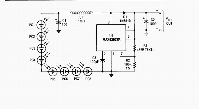
Build a Solar power supply