Saturday, October 25, 2014

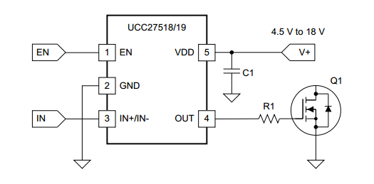
4A High Speed Low Side Gate Driver

The UCC27518 and UCC27519 single-channel, high-speed, low-side gate driver device is capable of effectively driving MOSFET and IGBT power switches. Using a design that inherently minimizes shoot-through current, UCC27518 and UCC27519 are capable of sourcing and sinking high, peak-current pulses into capacitive loads offering rail-to-rail drive capability and extremely small propagation delay typically 17 ns.

The UCC27518 and UCC27519 provide 4-A source, 4-A sink (symmetrical drive) peak-drive current capability at VDD = 12 V. The UCC27518 and UCC27519 are designed to operate over a wide VDD range of 4.5 V to 18 V and wide temperature range of -40°C to 140°C. Internal Under Voltage Lockout (UVLO) circuitry on VDD pin holds output low outside VDD operating range.
Circuit Project: 4A High-Speed Low-side Gate Driver
Features
  • Low-Cost, Gate-Driver Device Offering Superior Replacement of NPN and PNP Discrete Solutions
  • Pin-to-Pin Compatible With TI’s TPS2828 and the TPS2829
  • 4-A Peak Source and 4-A Peak Sink Symmetrical Drive
  • Fast Propagation Delays (17-ns typical)
  • Fast Rise and Fall Times (8-ns and 7-ns typical)
  • 4.5-V to 18-V Single Supply Range
  • Outputs Held Low During VDD UVLO (ensures glitch free operation at power-up and power-down)
  • CMOS Input Logic Threshold (function of supply voltage with hysteresis)
  • Hysteretic Logic Thresholds for High Noise Immunity
  • EN Pin for Enable Function (allowed to be no connect)
  • Output Held Low when Input Pins are Floating
  • Input Pin Absolute Maximum Voltage Levels Not Restricted by VDD Pin Bias Supply Voltage
  • Operating Temperature Range of -40°C to 140°C
  • 5-Pin DBV Package (SOT-23)
Device Uses
  • Switch-Mode Power Supplies
  • DC-to-DC Converters
  • Companion Gate Driver Devices for Digital Power Controllers
  • Solar Power, Motor Control, UPS
  • Gate Driver for Emerging Wide Band-Gap Power Devices (such as GaN)


Source by http://www.extremecircuits.net/2012/08/circuit-project-4a-high-speed-low-side.html
Read More..

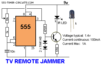
TV Remote Control Jammer

This circuit confuses the infra-red receiver in a TV. It produces a constant signal that interferes with the signal from a remote control and prevents the TV detecting a channel-change or any other command. This allows you to watch your own program without anyone changing the channel !!    The circuit is adjusted to produce a 38kHz signal. The IR diode is called an Infra-red transmitting Diode or IR emitter diode to distinguish it from a receiving diode, called an IR receiver or IR receiving diode. (A Photo diode is a receiving diode).

Circuit Project: TV REMOTE CONTROL JAMMER Circuit

There are so many IR emitters that we cannot put a generic number on the circuit to represent the type of diode. Some types include: CY85G, LD271, CQY37N (45¢), INF3850, INF3880, INF3940 (30¢). The current through the IR LED is limited to 100mA by the inclusion of the two 1N4148 diodes, as these form a constant-current arrangement when combined with the transistor and 5R6 resistor.
Read More..

Zapper Refurbisher Ni Cad Battery Circuit Diagram

Zapper Refurbisher Ni-Cad Battery Circuit Diagram. Batteries and Nickel Cadmium, or simply Ni-Cad NiCad NiCd or sometimes do not work as expected, has no voltage or current, can not be recharged, it means that the battery is internally shorted or partially damaged. You can retrieve this battery in many ways, either by chemical or electrical recovery. One is simpler and recondition the Ni-Cad battery using a zapper circuit.

This circuit restores the Ni-Cad battery short circuit, forcing a high current flow to burn the dirt inside. The resistance of 120 ohm per 10W is used to limit the load current of the capacitor. After zapping the battery goes to the load position, the charging process will take a long time and is indicated by the LED, which will gradually increase the brightness intensity until stable, so when the battery is fully charged.

The power supply for the circuit can be made ​​from a small transformer 350 mA to 1 A with a half-wave rectifier or full wave.

Zapper Refurbishes Ni-Cad Battery Circuit Diagram

Zapper Refurbisher Ni-Cad Battery Circuit Diagram

Read More..

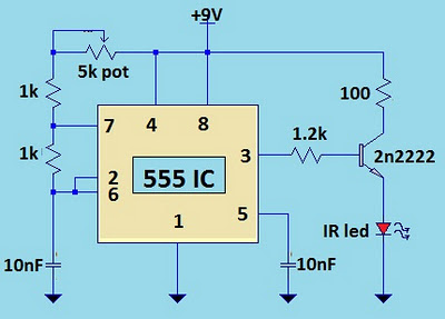
TV Remote Jammer Using 555 IC Circuit Diagram

The TV remote control transmits television signals as pulses of frequency around 37.5kHz. Each button on the remote control is pressed or equivalent has a pulse signal codes. This remote transmits pulses of the circuit block of the same frequency as the remote to your TV confuse decoding the transmitted signal.

The heart of the circuit is the 555 timer IC in astable circuit works mode.The output series of pulses at a frequency of 18 kHz to 48 kHz by simply adjusting the 5K potentiometer. What you do is adjust the potentiometer until frequeny jives to its distance from the TV or until the signal is ignored by television.

 TV Remote Jammer Using 555 IC Circuit Diagram

 TV Remote Jammer Using 555 IC Circuit Diagram


Read more IC Circuits
Read More..

Simple Stereo VU Meter

I like to see lights move to music. This project will indicate the volume level of the audio going to your speakers by lighting up LEDS. The LEDS can be any color so mix them up and really make it look good. The input of the circuit is connected to the speaker output of your audio amplifier. You want to build two identical units to indicate both right and left channels. The input signal level is adjusted by the 10k ohm VR. If you wish to make a very large scale model of this unit and hang it on your wall there is an optional output transistor that can drive many LEDS at once. The unit I built drove three LEDS for each output. The sequence of the LEDS lighting are as follows Pin 1, 18, 17, 16, 15, 14, 13, 12, 11, 10.


Read More..

High Performance Interruption Detector

High-Performance Interruption Detector. The circuit presented here detects interruption in security systems. Its features include no false triggering by external factors (such as sun-light and rain), easy relative positioning of the sensors and alignment of the circuit, high sensitivity, and reliability. The circuit comprises three sections, namely, transmitter, receiver, and power supply. The transmitter generates modulated IR signals and the receiver detects the change in IR intensity. Power supply provides regulated +5V to the transmitter and the receiver. 

The power supply and the speaker are kept inside the premises while the transmitter and the receiver are placed oppo site to each other at the entrance where the detection is needed. Three connections (Vcc, GND, and SPKR) are needed from the power supply/speaker to the receiver section, while only two connections (Vcc and GND) are required to the transmitter. The transmitter is basically an astable multivibrator configured around NE555 (IC3). Its frequency should match the frequency of the detector/sensor module (36 kHz for the module shown in figure) in the receiver. The transmitter frequency is adjusted by preset VR2. For making the duty cycle less than 50 per cent, di-ode 1N4148 is connected in the charging path of capacitor C7. 

The output of astable multivibrator modulates the IR signal emitted from IR LEDs that are used in series to obtain a range of 7 metres (maximum). To increase the range any further, the transmitted power has to be raised by using more number of IR LEDs. In such a case, it is advisable to use another pair of IR LEDs and 33-ohm series resistor in parallel with the existing IR LEDs and resistor R5 across points X and Y. The receiver unit consists of a monostable multivibrator built around NE555 (IC2), a melody generator, and an IR sensor module. The output of the IR sensor module goes high in the standby mode or when there is continuous presence of modulated IR signal.
High-Performance Interruption Detector Circuit diagram :
. 
High-Performance-Interruption-Detector-Circuit-Diagram
High-Performance Interruption Detector Circuit Diagram
 
When the IR signal path is blocked, the output of the sensor module still re-mains high. However, when the block is removed, the output of the sensor module briefly goes low to trigger monostable IC3. This is due to the fact that the sensor module is meant for pulsed operation. Thus interruption of the IR path for a brief period gives rise to pulsed operation of the sensor module. Once monostable IC2 gets triggered, its output goes high and stays in that state for the duration of its pulse width that can be controlled by preset VR1. The high output at pin 3 of the monostable makes the musical IC to function. Voltage divider comprising R2 and R3 reduces the 555 output voltage to a safer value (around 3V) for UM66 operation. The du-ration of the musical notes is set by pre-set VR1 as stated earlier. 

For proper operation of the circuit, use 7.5V to 12V power supply. A battery backup can be provided so that the circuit works in the case of power failure also. Potmeter VR3 serves as a volume control. The transmitter, receiver, and power supply units should be assembled separately. The transmitter and the receiver should have proper coverings (booster) for protection against rain. The length of the wire used for connecting the IR sensor module and IR LEDs should be minimum. 

Note. 
 
The heart of the circuit is the IR sensor module (usually used in VCRs and TVs with remote); the circuit works satisfactorily with various makes of sensors. The entire circuit can be fixed in the same cabinet if the connection wires to the sensors are smaller than 1.5 meters. The reflection property of IR signals can also be used for small distance coverage.
Read More..

Build 12V to 9V DC Converter

To get a more precise output voltage, replace zener diode Z1 with 10V and R1 with a 1Kilo ohm potentiometer. A Coolrib for Q1 is optional but highly recommended. You can replace Q1 for a more robust type to get more output amps depending on your requirements. Simple circuit to power your 9 volt cassette recorder and other stuff.


Parts List:

R1 = 560 ohm
C1 = 1000uF/40V, Electrolytic
C2 = 10uF/25V, Electrolytic
C3 = 330nF, Ceramic
Z1 = 9.1V, 1watt zener
Q1 = ECG184, NTE184 
Read More..