Wednesday, November 12, 2014
6 V to 12 V Power Supply Inverter
Part List:
R1, R4 2.2K 1/4W Resistor
R2, R3 4.7K 1/4W Resistor
R5 1K 1/4W Resistor
R6 1.5K 1/4W Resistor
R7 33K 1/4W Resistor
R8 10K 1/4W Resistor
C1,C2 0.1uF Ceramic Disc Capacitor
C3 470uF 25V Electrolytic Capcitor
D1 1N914 Diode
D2 1N4004 Diode
D3 12V 400mW Zener Diode
Q1, Q2, Q4 BC547 NPN Transistor
Q3 BD679 NPN Transistor
L1 See Notes
MISC Heatsink For Q3, Binding Posts (For Input/Output), Wire, Board

Monday, October 20, 2014
12 Vdc 120 Vac Inverter Circuit Diagram
This Inverter takes 12 volt d.c and steps it up to 120 volt a.c. The wattage depends on which transistors you use for Q1 and Q2, as well as the "Amp Rating" of the transformer you use for T1. This inverter can be constructed to supply anywhere from 1 to 1000 (1 KW) watts. If Q1, Q2 are 2N3055 NPN Transistors and T1 is a 15 A transformer, then the inverter will supply about 300 watts. Larger transformers and more powerful transistors can be substituted for T1, Q1 and Q2 for more power. Note: Dont try to run inductive loads (motors...) off this inverter.

Parts:
C1, C2 68 uf, 25 V Tantalum Capacitor
R1, R2 10 Ohm, 5 Watt Resistor
R3, R4 180 Ohm, 1 Watt Resistor
D1, D2 HEP 154 Silicon Diode
Q1, Q2 2N3055 NPN Transistor (see "Notes")
T1 24V, Center Tapped Transformer
Misc. Wire, Case, Receptacle (for output)
Fuses, Heatsinks, etc.
Caution: This circuit can cause serious injury or death. Keep away from children.
Friday, October 3, 2014
Mosfet 1000 Watt Power Inverter
This power inverter circuit will provide a very stable “Square Wave” Output Voltage. Frequency of operation is determined by a pot and is normally set to 60 Hz. Various “off the shelf” transformers can be used. Or Custom wind your own for best results.
Additional MosFets can be paralleled for higher power. It is recommended to Have a “Fuse” in the Power Line and to always have a “Load connected”, while power is being applied. The Fuse should be rated at 32 volts and should be aproximately 10 Amps per 100 watts of output. The Power leads must be heavy enough wire to handle this High Current Draw! appropriate Heat Sinks Should be used on the RFP50N06 Fets. These Fets are rated at 50 Amps and 60 Volts. Other types of Mosfets can be substituted if you wish.
There ARE Limitations! I have had numerous requests for an Inverter for 1000 watts and Even MORE. Sorry I Don’t feel this is Practical. At 1000 Watts and operating from a 12 Volt Source, the Input Current will be close to 100 AMPS. That would Require a HUGH Size of a Primary Wire.
Wednesday, September 24, 2014
Simple Power inverter is Bidirectional Circuit Diagram
When the circuit starts up, the substrate diode of the output FET bootstraps the output voltage to the point where synchronous switching takes over. When the gate-switching signal is symmetrical, the output voltage is approximately -95% of the input voltage, and the efficiency is greater than 80%. You can obtain voltage step-up or step-down by adjusting the switching ratio.
Power inverter is Bidirectional Schematic

When I used the circuit between two 4V lead-acid batteries, a comparator adjusted the switch ratio to drive charge in the desired direction. The circuit automatically replaces charge drained from one battery to the other. In a short-battery-life application, the 2.5-mA standby current from each battery may be negligible. Using lower-gate-capacitance, FETs can reduce losses. Alternatively, you can add gates to the drive circuit to turn off both FETs whenever the battery voltages balance.
The minimum input voltage is a function of the gate thresholds of the FETs. The ±9V rating of the CMOS 555 timer sets the maximum voltage. My prototype supplies approximately 100 mA Link
Wednesday, September 10, 2014
AOC A240 WD LCD MONITOR SMPS and BACK LIGHT INVERTER SCHEMATIC


Saturday, August 16, 2014
6V to 220V inverter schematic
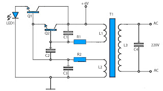
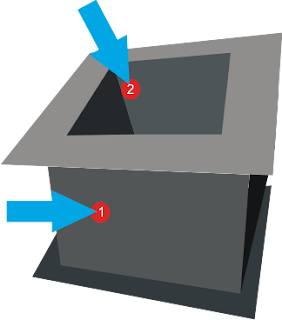

4 : Ferrite or iron rods which are mounted on the hole.
To coil L1 as much as 70 times, L2 200 times, And L3 as much as 1000 times.
L1 wire diameter 1mm
L2 wire diameter 0.8mm
L3 wire diameter 0.4 mm