Showing posts with label supply. Show all posts

Wednesday, November 19, 2014

Power Supply with tube

Power supply with Z2C tubes are designed specifically to provide power supply voltage to the EL-34 tube amplifier push-pull in the previous article. Power supply with Z2C tube to tube power amplifier is made with a tube rectifier Z2C. Just as the power supply for power amplifier tube earlier, power supply also uses a filter 3 levels with kapsitor electrolyte. Circuit power supply with tube rectifier Z2C can give +210 VDC output voltage. A complete range of power supply for power amplifier tube can be seen in thethe following figure .


Power Supply with tube


Z2C on the rectifier tube in power supply with tube above require a supply voltage for the filaments taken from the other side of the transformer secondary. Power supply with Z2C tube is a power supply that dapt used as a substitute power supply for power amplifier tubes .
Read More..

Monday, November 17, 2014

Protection of the Mosfet in flyback power supply

PKC-136 PEAK CLAMP CHARACTERISTICS VBR 160Vdc VDRM 700Vdc P 1.5W. See Circuits Diagram below :


Protection of the Mosfet in flyback power supply  
Feature :
- Protection of the Mosfet in flyback power supply
TRANSIL™ and blocking diode in a single package BENEFITS
- Accurate voltage clamping regardless load
- Reduced current loop
- Reduced EMI emission
- High integration
- Fast assembly
- Reduced losses in stand by mode

Read More..

Wednesday, November 12, 2014

6 V to 12 V Power Supply Inverter

This inverter circuit can provide up to 800mA of 12V power from a 6V supply. For example, you could run 12V car accessories in a 6V (British?) car. The circuit is simple, about 75% efficient and quite useful. By changing just a few components, you can also modify it for different voltages.


6 V to 12 V Power Supply Inverter Circuit Diagram

Part List:


R1, R4 2.2K 1/4W Resistor
R2, R3 4.7K 1/4W Resistor
R5 1K 1/4W Resistor
R6 1.5K 1/4W Resistor
R7 33K 1/4W Resistor
R8 10K 1/4W Resistor
C1,C2 0.1uF Ceramic Disc Capacitor
C3 470uF 25V Electrolytic Capcitor
D1 1N914 Diode
D2 1N4004 Diode
D3 12V 400mW Zener Diode
Q1, Q2, Q4 BC547 NPN Transistor
Q3 BD679 NPN Transistor
L1 See Notes
MISC Heatsink For Q3, Binding Posts (For Input/Output), Wire, Board
Read More..

Thursday, November 6, 2014

1 2 volts power supply

This switch mode power supply circuit require an input voltage range , between 4.5V to 16V,and will provide a very stable output voltage of 1.2 volt . The LTM4627 supports an output voltage range of 0.6V to 5V, set by a single external resistor , so you can modify the output voltage .

High switching frequency and a current mode architecture enable a very fast transient response to line and load changes without sacrificing stability.
 
1.2 volts power supply
Read More..

Sunday, November 2, 2014

3V DC to 5V DC REGULATED POWER SUPPLY ELECTRONIC DIAGRAM


3V DC to 5V DC REGULATED POWER SUPPLY ELECTRONIC DIAGRAM

A 5V DC regulated output from 2 cells 3V DC batteries. The output current of the circuit is limited to 50mA. However, it still able to supply many microcontroller circuits. 3009 and 560R Resistor provide the 5V DC output, make up a voltage divider network.
Read More..

Saturday, November 1, 2014

General DC Power Supply with uA723 This is the power supply circuit for general purpose usage General Power Supply with uA723 circuit diagram The s

General DC Power Supply with uA723

This is the power supply circuit for general purpose usage.
General


The supply can be used for supply output voltages from 1 to 35V. The line transformer should be selected to give about 1.4 times the desired output voltage from the positif side of filted capacitor C1 to ground. Potensiometer R2 sets the output voltage to the desired value by adjusting the reference input. Rsc is the current limit set resistor.

For example, if the maximum current output is to be 1A, Rsc=0.65/1.0 = 0.65 Ohm. The 1KOhm resistor,R5, is a light-loaded resistor designed to improve the no-load stability of the supply.
Read More..

Saturday, October 25, 2014

How To Build Regulated Power Supply with Stability at 3A

The circuit was designed to build a Regulated Power Supply with Stability at 3A will provide a regulated voltage from 40 V to 70 V in a 3 A current.
  • 2N3055 – a complementary Silicon Epitaxial-Base planar NPN transistor mounted in Jedec TO-3 metal case for use as power transistor.
  • BD243 – an epitaxial-base Silicon NPN transistor intended for wide variety of high speed switching and power amplifier applications such as series and shunt regulators, and driver and output stages of high-fidelity amplifiers.
  • BC303 – a PNP silicon planar epitaxial transistor used for AF drivers & outputs, for AF medium power amplifiers, and for switching applications up to 1 A.

There are times when some applications are requiring a regulated power supply that has relatively high output voltage and stability. All of these features are being attained in the design of this circuit. The voltage output of the circuit can range from 40 V up to 60 V while carrying a current of 3 A while providing stabilization. The construction of the circuit is very simple since the components used were available easily in the market. The only thing that matters is how the connection will be ensured.

During the operation, when the circuit is delivering 50 V up to 60 V, the transistor Q1 will be hot enough and would require a large heatsink. For voltage output higher than 50 V up to 70 V, the stability of the circuit may be found unsatisfactory. This is the reason why the ideal output voltage of the circuit is 45 V up to 60 V. In order to alter the output voltage from 40 V up to 70 V, a 470 Ohms potentiometer RV1 is used for the adjustments. However, the potentiometer may also be replaced by two constant resistors with suitable values when the circuit adjustment has been done. This is due to the fact that the use of a potentiometer may lead to a 3 V of over voltage.
 
 As a reminder, the positive output of the circuit should be connected at point A while the 0 V output should be connected at point B. The 0 V reference should not be connected to the ground for the circuit to function properly. the use of this 3 A power supply with an average of 50 V circuit may be found on various applications that normally requires this rating.

Since this type of circuit is easily built, it is being utilized in industrial, educational, clinical, and laboratory facilities. It may come with different additional features such as reduced ripple & noise, overload protection, and short circuit & high current protection.
Read More..

Thursday, October 23, 2014

Build a Solar power supply

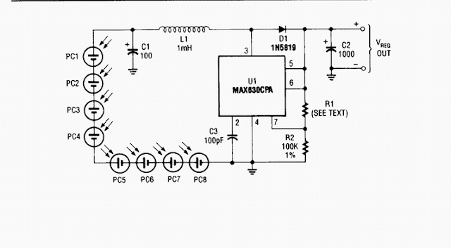
Here is Solar power supply circuit delivers either 4.8 or 7.2 V regulated at 15 mA with a 3-V input from a bank of photocells. Rl should be 453 kQ for a 7.2-V output and 274 РЁ for a 4.8-Vdc output. Regulator efficiency is around 70%. This should be considered when selecting suitable solar cells.

Circuit Diagram

Build a Solar power supply

Read More..

Thursday, October 9, 2014

Improved 240 VAC TO 5 VDC POWER SUPPLY

This is simple way to power some 5v logic from a 240vac source. If a 120vac power adapter is used, the circuit will also work for 120vac power lines.


Read More..

Wednesday, September 24, 2014

Soft Start For Switching Power Supply

Switching power supply whose output voltage is appreciably lower than its input voltage has an interesting property: the current drawn by it is smaller than its output current. However, the input power (UI) is, of course, greater than the output power. There is another aspect that needs to be watched: when the input voltage at switch-on is too low, the regulator will tend to draw the full current. When the supply cannot cope with this, it fails or the fuse blows. It is, therefore, advisable to disable the regulator at switch-on (via the on/off input). until the relevant capacitor has been charged. When the regulator then starts to draw current, the charging current has already dropped to a level which does not overload the voltage source.

Circuit diagram:Soft Start Circuit Diagram For Switching Power Supply
Soft Start Circuit For Switching Power Supply

The circuit in the diagram provides an output voltage of 5 V and is supplied by a 24 V source. The regulator need not be disabled until the capacitor is fully charged: when the potential across the capacitor has reached a level of half or more of the input voltage, all is well. This is why the zener diode in the diagram is rated at 15 V. Many regulators produced by National Semiconductor have an integral on/off switch, and this is used in the present circuit. The input is intended for TTL signals, and usually consists of a transistor whose base is accessible externally. This means that a higher switching voltage may be applied via a series resistor: the value of this in the present circuit is 22 kΩ. When the voltage across the capacitor reaches a level of about 17 V, transistor T1 comes on, whereupon the regulator is enabled.
 
 
Source: National Semiconductors
Read More..

Low Dropout Adjustable Breadboard Power Supply

This project details the design of a very low dropout adjustable power supply. A good power supply is essential to electronic projects. While there are many existing designs for adjustable power supplies, this one makes improvements that make it more useful for hobby designs

Very Low Dropout Adjustable Breadboard Power SupplyMIC2941 regulator has guaranteed 1.25A output
Low dropout, only 40mV - 400mV compared to 1.25V - 2.0V for LM317. This means you can use a wider range of output voltages including generating 3.3V from as low as 3.7V (such as 3 AAs or a lithium ion battery)!
Short circuit and overheating protection
Input diode to protect circuitry from negative voltages or AC power supplies.
2.1mm DC jack and terminal connector for voltage inputs
Two indicator LEDs for high and low voltages
Output selection switch to select from 3.3v, 5v and Adjustable
On-board potentiometer for adjusting voltage from 1.25V up to within 0.5V of the input voltage. (20V max)
On/Off switch for entire board
Very Low Dropout Adjustable Breadboard Power Supply Circuit Diagram
Read More..

Transformerless Power Supply

This circuit will supply up to about 20ma at 12 volts. It uses capacitive reactance instead of resistance; and it doesnt generate very much heat.The circuit draws about 30ma AC. Always use a fuse and/or a fusible resistor to be on the safe side. The values given are only a guide. There should be more than enough power available for timers, light operated switches, temperature controllers etc, provided that you use an optical isolator as your circuits output device. (E.g. MOC 3010/3020) If a relay is unavoidable, use one with a mains voltage coil and switch the coil using the optical isolator.C1 should be of the suppressor type; made to be connected directly across the incoming Mains Supply.

They are generally covered with the logos of several different Safety Standards Authorities. If you need more current, use a larger value capacitor; or put two in parallel; but be careful of what you are doing to the Watts. The low voltage AC is supplied by ZD1 and ZD2. The bridge rectifier can be any of the small Round, In-line, or DIL types; or you could use four separate diodes. If you want to, you can replace R2 and ZD3 with a 78 Series regulator. The full sized ones will work; but if space is tight, there are some small 100ma versions available in TO 92 type cases. They look like a BC 547. It is also worth noting that many small circuits will work with an unregulated supply.

Circuit diagram:Transformerless Power Supply Circuit Diagram
Transformerless Power Supply Circuit Diagram

You can, of course, alter any or all of the Zenner diodes in order to produce a different output voltage. As for the mains voltage, the suggestion regarding the 110v version is just that, a suggestion. I havent built it, so be prepared to experiment a little. I get a lot of emails asking if this power supply can be modified to provide currents of anything up to 50 amps. It cannot. The circuit was designed to provide a cheap compact power supply for Cmos logic circuits that require only a few milliamps. The logic circuits were then used to control mains equipment (fans, lights, heaters etc.) through an optically isolated triac.

If more than 20mA is required it is possible to increase C1 to 0.68uF or 1uF and thus obtain a current of up to about 40mA. But suppressor type capacitors are relatively big and more expensive than regular capacitors; and increasing the current means that higher wattage resistors and zener diodes are required. If you try to produce more than about 40mA the circuit will no longer be cheap and compact, and it simply makes more sense to use a transformer. The Transformerless Power Supply Support Material provides a complete circuit description including all the calculations.

Web-masters Note:
I have had several requests for a power supply project without using a power supply. This can save the expense of buying a transformer, but presents potentially lethal voltages at the output terminals. Under no circumstances should a beginner attempt to build such a project.

Important Notice:
Electric Shock Hazard. In the UK,the neutral wire is connected to earth at the power station. If you touch the "Live" wire, then depending on how well earthed you are, you form a conductive path between Live and Neutral. DO NOT TOUCH the output of this power supply. Whilst the output of this circuit sits innocently at 12V with respect to (wrt) the other terminal, it is also 12V above earth potential. Should a component fail then either terminal will become a potential shock hazard.
MAINS ELECTRICITY IS VERY DANGEROUS.

If you are not experienced in dealing with it, then leave this project alone. Although Mains equipment can itself consume a lot of current, the circuits we build to control it, usually only require a few milliamps. Yet the low voltage power supply is frequently the largest part of the construction and a sizeable portion of the cost.


Author: Ron J - Copyright: Zen
Read More..

Sunday, September 21, 2014

Power Supply with principle of UPS

power
For UPS Power Supply circuit consists of lowering the voltage, rectifier, charger, batery and regulators. The technique is applied from UPS on the power supply is the use of batery and charger is connected dengang direct coupling with a series diode. For more details can be seen with the following image.
Read More..

Saturday, September 20, 2014

Simple 5V Regulated Power Supply Wiring diagram Schematic

5V Regulated Power Supply Circuit Diagram is a small +5V power supply, which is useful when experimenting with digital electronics. Small inexpensive wall tranformers with variable output voltage are available from any electronics shop and supermarket. Those transformers are easily available, but usually their voltage regulation is very poor, which makes then not very usable for digital schema experimenter unless a better regulation can be achieved in some way.

The following schema is the answer to the problem. This schema can give +5V output at about 150 mA current, but it can be increased to 1 A when good cooling is added to 7805 regulator chip. The schema has overload and thermal protection. The capacitors must have enough high voltage rating to safely handle the input voltage feed to schema. The schema is very easy to build for example into a piece of veroboard.

 5V Regulated Power Supply Circuit Diagram
Parts:

C1 = 100uF-25V electrolytic capacitor, at least 25V voltage rating
C2 = 10uF-25V electrolytic capacitor, at least 6-16V voltage rating
C3 = 100nF-63V ceramic or polyester capacitor
IC = 7805 regulator IC

ICs Pinout :
  1. Unregulated voltage in
  2. Ground (See Diagram)
  3. Regulated voltage out

Circuit features:
  • Gives out well regulated +5V output, output current capability of 100 mA
  • Built-in overheating protection shuts down output when regulator IC gets too hot
  • Very simple and easy to build
  • Very stable +5V output voltage, reliable operation
  • Easy to get components, uses only very common basic components
  • Based on datasheet example schema, I have used this schema succesfully as part of many electronics projects
  • Part of electronics devices, small laboratory power supply
  • Wide range of input unreglated DC 8-24V power supply
  • Few dollars for the electronics components + the input transformer cost

Modification Iideas

More output current:

If you need more than 150 mA of output current, you can update the output current up to 1A doing the following modifications.
  • Change the transformer from where you take the power to the schema to a model which can give as much current as you need from output
  • Put a heatsink to the 7805 regulator (so big that it does not overheat because of the extra losses in the regulator)

More output voltages:

If you need other voltages than +5V, you can modify the schema by replacing the 7805 chips with another regulator with different output voltage from regulator 78xx chip family. The last numbers in the the chip code tells the output voltage. Remember that the input voltage muts be at least 3V greater than regulator output voltage ot otherwise the regulator does not work well.

Read More..

Thursday, September 18, 2014

LM338 Power Supply 13 8V 5A

This ac to dc power supply can output 5A in continous operation and 12A peak current. This kind of dc power supplies uses a PCB so you can use two case types for IC1, TO-220 or TO-3. The regulation of this 12 volt power supply is made with TR1 ( multiturn ). IC1 must be placed on proper heatsink.

LM338 Power Supply Circuit Diagram :
 13.8V 5A power sp-Circuit Diagram
Read More..

Monday, September 8, 2014

Transformerless 5 Volt Power Supply Wiring diagram Schematic

Description

An increasing number of appliances draw a very small current from the power supply. If you need to design a mains powered device, you could generally choose between a linear and a switch-mode power supply. However, what if the appliance’s total power consumption is very small? Transformer-based power supplies are bulky, while the switchers are generally made to provide greater current output, with a significant increase in complexity, problems involving PCB layout and, inherently, reduced reliability. 

Is it possible to create a simple, minimum part-count mains (230 VAC primary) power supply, without transformers or coils, capable of delivering about 100 mA at, say, 5 V A general approach could be to employ a highly inefficient stabilizer that would rectify AC and, utilizing a zener diode to provide a 5.1 V output, dissipate all the excess from 5.1 V to (230×v2) volts in a resistor. Even if the load would require only about 10 mA, the loss would be approximately 3 watts, so a significant heat dissipation would occur even for such a small power consumption. 

At 100 mA, the useless dissipation would go over 30 W, making this scheme completely unacceptable. Power conversion efficiency is not a major consideration here; instead, the basic problem is how to reduce heavy dissipation and protect the components from burning out. The schema shown here is one of the simplest ways to achieve the above goals in practice. A JVR varistor is used for overvoltage/surge protection. Voltage divider R1-R2 follows the rectified 230 V and, when it is high enough, T1 turns on and T3 cannot conduct.

Circuit diagram:

Transformerless


When the rectified voltage drops, T1 turns off and T3 starts to conduct current into the reservoir capacitor C1. The interception point (the moment when T1 turns off) is set by P1 (usually set to about 3k3), which controls the total output current capacity of the power supply: reducing P1 makes T1 react later, stopping T3 later, so more current is supplied, but with increased heat dissipation. Components T2, R3 and C2 form a typical ‘soft start’ schema to reduce current spikes this is necessary in order to limit C1’s charging current when the power supply is initially turned on. At a given setting of P1, the output current through R5 is constant. 

Thus, load R4 takes as much current as it requires, while the rest goes through a zener diode, D5. Knowing the maximum current drawn by the load allows adjusting P1 to such a value as to provide a total current through R5 just 5 to 6 mA over the maximum required by the load. In this way, unnecessary dissipation is much reduced, with zener stabilization function preserved. Zener diode D5 also protects C1 from over voltages, thus enabling te use of low-cost 16 V electrolytics. 

The current flow through R5 and D5, even when the load is disconnected, prevents T3’s gate-source voltage from rising too much and causing damage to device. In addition, T1 need not be a high-voltage transistor, but its current gain should exceed 120 (e.g. BC546B, or even BC547C can be used).

CAUTION!

The schema is not galvanically isolated from the mains. Touching any part of the schema (or any schemary it supplies power to) while in operation, is dangerous and can result in an electric shock! This schema should not be built or used by individuals without proper knowledge of mains voltage procedures.


Copyright: Elektor Electronics Magazine
Author: Srdjan Jankovic & Branko Milovanovic
Read More..

Friday, September 5, 2014

Variable Power Supply with L200

This is adjustable power supply schematic diagram with IC L200 for its power regulation.

Variable


Voltage output is controlled by 10K variable resistor. Output voltage range value will be about 3 to 15 volts, and current range is about 10mA minimum and 2 amp maximum. Reaching the current limit will reduce the output voltage to zero.
Read More..

Tuesday, September 2, 2014

9V output switching power supply

By using the circuit you do not bother to roll  up a transformer that is used to reduce voltage AC 220V to 7V ,9 V or 12V, etc. When using a large transformer we will find it hard to make transformator. by rolling hundreds or even thousands of times roll. But if you use this circuit a little just enough to roll trafo not to small, and its be relatively small.
simple
Part List :
R1________________________________680K
R2________________________________47K
R3________________________________100R
R4________________________________1K
R5________________________________1R
D1,D2,D3,D4,D7,D8,D9,D10__________1N4007
D5,D6_____________________________1N4148
C1________________________________2u2F 400V
C2________________________________2n2
C3________________________________47uF 25V
C4________________________________10n
C5________________________________470uF / 16V
Q1________________________________MJE13003
Q2________________________________S8050

This is construction of transformer. For the first toll 220 times , then after that wrap right on top of L2 , and L3 on L2.
switching
Read More..

Sunday, August 31, 2014

2 5A 1 25 To 25V Regulated Power Supply Wiring diagram Schematic

This power supply uses an LM317J adjustable regulator and an MJ2955 pass transistor. Ql and U2 as well as Ul should be heats inked. A suitable heat-sink would typically be 4` 4` 1` fins, extruded type, because up to 65 W dissipation can occur. R8 and R9 should be 1% types or selected from 5% film types with an accurate ohmmeter. Capacitors are disc ceramic except for those with polarity marked, which are electrolytic. D1, D2—1-A, 100-PIV rectifier diode. DS1—Red LED. F1 —1,5-A, 3AG fuse in chassis-mount holder. J1, J2—Standard five-way binding post, one red, one black. M1—Milli-ammeter, 0-1 mA dc. Q1—NPN power transistor MJ2955 (Radio Shack) or equiv device with a + 70-V, 10-A, 150-W rating in a -204 case. R1, R2, R7—5-W wire-wound resistor. See Notes 3 and 4 for source, or, use 17 inches of no. 28 enam wire, single-layer wound, on a 10-KOhmhm, 1-W carbon-composition resistor for R1 and R7. For R2, use 36 inches of no. 30 enam wire on a 10-KOhmhm, 1-W carbon composition resistor (scramble wound). R-4—Panel-mount, 5-kfi, 2-W or 5-W potentiometer, carbon or wire wound (See Note 8). R8, R9—See text. 51—SPST toggle switch. 52—DPDT toggle or rotary wafer switch. T1—25.2-V, 2.75-A power transformer (see text). U1—6-A, 200 PIV bridge rectifier with heat sink. See text. U2—LM317T +1.25- to 30-V, 1.5-A 7-220 regulator. Use an LM317HVK (T0-204 case) for dc output voltage greater than 40. See text.

2.5A-1.25 To 25V Regulated Power Supply Circuit Diagram

2.5A-1.25

Read More..

Saturday, August 30, 2014

15 V output regulated power supply circuit with uA723 and 2N3055

The supply receive from 220 /120/110 Volt AC , then lowered by the transformer . Then receives +20 Volts DC from rectifier / filter section. This applied to pin 11 and 12 of the IC uA723/LM723 , as well as to the collector of the 2N3055 series pass transistor. The output through R1 and R2, providing about 7 V with respect to ground at pin 4. The reference terminal at pin 6 is tied directly to pin 5 , the non inverting input of the error amplifier . For fine trimming the output voltage , a potentiometer can be installed between R1 and R2. A 100-pF capacitor from pin 13 to pin 4 furnishes gain compensation for the amplifier.
Base drive to the 2N3055 pass transistor is furnishes by pin of the uA723. Since desired output of the supply is 1 Ampere, maximum current limit is set to 1,5 Ampere by resistor Rsc whose value is 0,422 Ohm. A 100uF electrolytic capacitor is used for ripple voltage reduction at the output. A 1 kOhm output resistor provides stability for the power supply under no - load conditions. The 2N3055 pass transistor must be mounted on an adequate heatsink.
Read More..