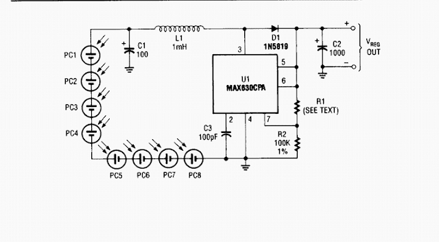
Solar Cell Array Charger with Regulator circuit can be used to charge batteries from a solar cell array. The circuit consists of an oscillator, a DC-DC step-up or ‘boost’ converter and a regulator that pro-vides regulation of the output voltage.The oscillator is built around a hex Schmitt trigger inverter IC, the 40106B, one resistor, R1, inserted between the input and the output of one of the gates in the 40106 to supply charge to C3. Depending on the values of resistor R1 and capacitor C3 you’re using in the circuit, the oscillator will operate at different frequencies, but a frequency below 100 kHz is recommended.
By consequence, the oscillator frequency should not exceed the maximum ripple frequency of capacitor C2 connected on the output. C2 should be an electrolytic capacitor with a DC working voltage larger than the desired output voltage. Besides, it should have a low ESR (equivalent series resistance).
Solar Cell Array Charger with Regulator Circuit Diagram :
IC1A is used as a buffer, ensuring that the oscillator sees a light, fairly constant load and so guaranteeing that the output frequency remains stable (within limits, of course). VCC of the Schmitt trigger can be connected directly to the battery charged, provided the charged batter y voltage does not exceed the max. or min. limits of the Schmitt trigger’s supply voltage. This ensures the Schmitt trigger can operate even if little power is obtained from the solar cell array.
When transistor T2 is turned on, (output from oscillator buffer IC1A is high), a collector current flows through inductor L1 which stores the energy as a magnetic field and creates a negative voltage VL1. When transistor T2 is switched off, (output from oscillator buffer IC1A is low), the negative voltage VL1 switches polarity and adds to the voltage from the solar cell array. Consequently, current will now flow trough the inductor coil L1 via diode D1 to the load (capacitor C2 and possibly the battery), irrespective of the output voltage level.
Capacitor C2 and/or the battery will then be charged. So, in the steady state the out-put voltage is higher than the input voltage and the coil voltage VL1 is negative, which leads to a linear drop in the current flowing through the coil. In this phase, energy is again transferred from the coils to the out-put. Transistor T2 is turned on again and the process is repeated. A type BC337 (or 2N2222) is suggested for T2 as it achieves a high switching frequency. Inductor L1 should have a saturation current larger than the peak current; have a core material like ferrite (i.e. high-frequency) and low-resistance. Diode D1 should be able to sustain a forward current larger than the maxi-mum anticipated current from the source. It should also exhibit a small forward drop and a reverse voltage spec that’s higher than the output voltage. If you can find an equivalent Schottky diode in the junk box, do feel free to use it.
The most important function of the shunt regulator around T1 is to protect the batteries from taking damage due to overcharging. Besides, it allows the output voltage to be regulated. Low-value resistor R3 is switched in parallel with the solar cell array by T1 so that the current from the solar cell array flows through it. Zener diode D2 is of course essential in this circuit as its zener voltage limits the output voltage when T1 should be turned on, connecting the solar cell array to ground via R3. In this way, there is no input voltage to the boost converter and the battery cannot be overcharged.
Sealed lead-acid (SLA) batteries with a liquid electrolyte produce gas when over-charged, which can ultimately result in damage to the battery. So, it’s important to choose the right value for zener diode D2. Special lead-acid batteries for solar use are available, with improved charge-discharge cycle reliability and lower self-discharge than commercially-available automotive batteries.
Finally, never measure directly on the out-put without a load connected the ripple current can damage your voltmeter (unless it’s a 1948 AVO mk2). Link