Saturday, October 25, 2014
12 Volt Battery Guardian
Dont get caught with a flat battery; this easy-to-build circuit can cut off the power to a 12V fridge or car stereo system if the battery voltages drops below critical level. Electric fridges in vans and 4WDs are a great idea but if you are not careful, they can severely discharge the battery and leave you stranded. Maybe the battery will end up with severe damage as well. The same problem applies if you have a big stereo system and you like to play it without the motor running.

Main features:
- Cuts power to load (eg, fridge) when battery voltage drops below a preset level.
- 10A rating.
- Low power drain.
- Chirping sound during cut-out.
- Flashing LED indication during cut-out.
- Automatically reconnects power when battery recharged.
Operation on 12V is fine when the motor is running and battery charge is maintained but if the fridge is allowed to run for too long when the motor is stopped, it can flatten the battery in a relatively short time. This is where the Battery Guardian comes into play. It monitors the battery voltage and disconnects power to the fridge before the battery becomes too flat to allow the engine to be started again.
Parts layout:

PCB layout:

Circuit diagram:


Source: Silicon Chip 6 May 2002

Simple Electro meter circuit
This is a simple electro meter circuit.This circuit will detect electrostatic charge from the any material such plastic,comb etc.
It can measure up to 30 cm from the target material.
To use this circuit first adjust R2 when the antenna near the material until Amp meter read 1 mA. Link
It can measure up to 30 cm from the target material.
To use this circuit first adjust R2 when the antenna near the material until Amp meter read 1 mA. Link

RF Transmitter using LM317 Circuit Diagram
This is the simple RF Transmitter using LM317 Circuit Diagram. Already we saw that the LM317 has hundreds of utilities besides a voltage regulator, how in this article of a audio amplifier with the LM317. Now that circuit the LM317 works for transmit radio waves in CW. The transmitter was done by SM0VPO and works very well, only not found the description the coil.
RF Transmitter using LM317 Circuit Diagram

If you liked this article,Take a few Seconds to Share this and leave comments
RF Probe for Multimeter Circuit Diagram
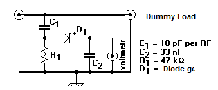
This is the RF Probe for Multimeter Circuit DiagramTo measure the RF voltage in a circuit to convert the signal unless they RF voltmeter. This conversion may be done with a very simple circuit, called a point or RF probe. A tip for RF Multimeter has to be made in a metal box with two connectors, one that receives the RF signal and another that goes to the multimeter.
In the case of this circuit the signal passes through two connectors between them and the RF signal is picked up.This signal passes through a 18 pF capacitor, a diode germanium, a resistor of 47 kOhm, and a bypass capacitor 33 nF. The anode of the diode is connected to the positive lead of the voltmeter and the other to ground.
RF Probe for Multimeter Circuit Diagram
Make a Photodiode Alarm
This Photodiode based Alarm can be used to give a warning alarm when someone passes through a protected area. The circuit is kept standby through a laser beam or IR beam focused on to the Photodiode. When the beam path breaks, alarm will be triggered.
The circuit uses a PN Photodiode in the reverse bias mode to detect light intensity. In the presence of Laser / IR rays, the Photodiode conducts and provides base bias to T1. The NPN transistor T1 conducts and takes the reset pin 4 of IC1 to ground potential. IC1 is wired as an Astable oscillator using the components R3, VR1 and C3. The Astable operates only when its resent pin becomes high. When the Laser / IR beam breaks, current thorough the Photodiode ceases and T1 turns off. The collector voltage of T1 then goes high and enables IC1. The output pulses from IC1 drives the speaker and alarm tone will be generated.
The circuit uses a PN Photodiode in the reverse bias mode to detect light intensity. In the presence of Laser / IR rays, the Photodiode conducts and provides base bias to T1. The NPN transistor T1 conducts and takes the reset pin 4 of IC1 to ground potential. IC1 is wired as an Astable oscillator using the components R3, VR1 and C3. The Astable operates only when its resent pin becomes high. When the Laser / IR beam breaks, current thorough the Photodiode ceases and T1 turns off. The collector voltage of T1 then goes high and enables IC1. The output pulses from IC1 drives the speaker and alarm tone will be generated.
Photo-Diode Alarm Circuit


How To Build Regulated Power Supply with Stability at 3A
The circuit was designed to build a Regulated Power Supply with Stability at 3A will provide a regulated voltage from 40 V to 70 V in a 3 A current.
- 2N3055 – a complementary Silicon Epitaxial-Base planar NPN transistor mounted in Jedec TO-3 metal case for use as power transistor.
- BD243 – an epitaxial-base Silicon NPN transistor intended for wide variety of high speed switching and power amplifier applications such as series and shunt regulators, and driver and output stages of high-fidelity amplifiers.
- BC303 – a PNP silicon planar epitaxial transistor used for AF drivers & outputs, for AF medium power amplifiers, and for switching applications up to 1 A.
There are times when some applications are requiring a regulated power supply that has relatively high output voltage and stability. All of these features are being attained in the design of this circuit. The voltage output of the circuit can range from 40 V up to 60 V while carrying a current of 3 A while providing stabilization. The construction of the circuit is very simple since the components used were available easily in the market. The only thing that matters is how the connection will be ensured.
During the operation, when the circuit is delivering 50 V up to 60 V, the transistor Q1 will be hot enough and would require a large heatsink. For voltage output higher than 50 V up to 70 V, the stability of the circuit may be found unsatisfactory. This is the reason why the ideal output voltage of the circuit is 45 V up to 60 V. In order to alter the output voltage from 40 V up to 70 V, a 470 Ohms potentiometer RV1 is used for the adjustments. However, the potentiometer may also be replaced by two constant resistors with suitable values when the circuit adjustment has been done. This is due to the fact that the use of a potentiometer may lead to a 3 V of over voltage.

As a reminder, the positive output of the circuit should be connected at point A while the 0 V output should be connected at point B. The 0 V reference should not be connected to the ground for the circuit to function properly. the use of this 3 A power supply with an average of 50 V circuit may be found on various applications that normally requires this rating.
Since this type of circuit is easily built, it is being utilized in industrial, educational, clinical, and laboratory facilities. It may come with different additional features such as reduced ripple & noise, overload protection, and short circuit & high current protection.
Since this type of circuit is easily built, it is being utilized in industrial, educational, clinical, and laboratory facilities. It may come with different additional features such as reduced ripple & noise, overload protection, and short circuit & high current protection.
LED Clock Using PIC 11 SP
Now youll be able to perpetually grasp the precise time. With this style youll be able to have an atomic clock in your area. Isn’t that great? scan on to grasp additional.

First of all, its not regarding any radioactive components here. this can be regarding building a clock show that may get the time from the DCFF77 facilities in Frankfurt, Germany.All thats required may be a clock LED show, DCFF77 receiver, and a microcontroller at the side of the mandatory connections.
Basically, the project permits a sign thats sent by the DCFF77 radio station to be decoded. After that. the microcontroller method it and sends it to the LED show to indicate the precise time. theres no got to build a sign receiver, an honest quality receiver may be bought on the net for a coffee worth.
Basically, the project permits a sign thats sent by the DCFF77 radio station to be decoded. After that. the microcontroller method it and sends it to the LED show to indicate the precise time. theres no got to build a sign receiver, an honest quality receiver may be bought on the net for a coffee worth.
Once everything has been set within the affiliation board the PIC supply code ought to be developed. The orientation of the antenna ought to be perpendicular to Frankfurt. itll receive signal if its among 2000 miles from town. If theres a sign, the amount on the clock LED show can blink during a constant rhytm. When a full cycle of binary pulses is received, the clock can show the precise time.
Subscribe to:
Posts (Atom)